Table of Contents
Advertisement
Quick Links
Advertisement
Table of Contents

Related Manuals for LUMENIS Array LaserLink


Summary of Contents for LUMENIS Array LaserLink
- Page 1 Delivery Device Operator Manual...
- Page 2 Under copyright laws, this manual may not be copied in whole or in part or reproduced in any other media without the express written permission of Lumenis, Inc. Permitted copies must carry the same proprietary and copyright notices as were affixed to the original.
-
Page 4: Table Of Contents
● Operation Contents Operation ....................6 Introduction ....................7 Array LaserLink Components ..............8 Array LaserLink Module ................. 8 Console......................8 Touchscreen Display..................8 Remote Touchpad ..................8 3D Mouse ...................... 8 Array LaserLink Installation ..............10 Connecting an Eye Safety Filter ..............13 Installing Observation Equipment .............. - Page 5 ● Operation Setting the Aiming Beam Intensity ............... 27 Setting the Duration ..................27 Setting the Interval ..................28 Setting the Treatment Beam Wavelength ............ 28 Resetting the Shot Counter ................29 Selecting the Fundus Lens ................30 Selecting the Laser Status ................31 Setting System Options ................
- Page 6 ● Operation Maintenance ................... 45 Troubleshooting Guide ................46 Error Messages ..................50 User Maintenance ..................51 Inspecting the Delivery Device Components ..........51 Clean the External Surface of the Delivery Device ........51 Annual Maintenance ..................51 Changing the Console Fuses ..............52 Electromagnetic Compatibility ..............
-
Page 7: Operation
● Operation Operation... -
Page 8: Introduction
Your local Lumenis Representative initially unpacks, inspects, sets up, and installs the Array to ensure that it is working properly. In addition, Lumenis provides in-service training to ensure that your surgical staff is experienced in the performance and safety considerations of the device. -
Page 9: Array Laserlink Components
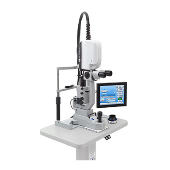
Optional co-observation devices are also available. System connections and controls are described in the following pages. Array LaserLink Module The Array LaserLink module attaches to the Slit Lamp and delivers the treatment beam to the target tissue. Console The console houses the control electronics and power supply, and integrates the Array LaserLink module with the laser system. - Page 10 ● Operation Fig. 1 Doctor and patient positioning Array Module Touchscreen Eye Safety Display Filter (not part of the Array, but required for safe Array Console operation) Remote Touchpad Fig. 2 Array LaserLink Components (3D Mouse not displayed)
-
Page 11: Array Laserlink Installation
Connecting to anything else will result in a non- functioning delivery device. The Array LaserLink consists of the four components which are shown in Fig. 2 on the previous page. The touch screen and touch pad\3D mouse are mounted by a qualified service technician at a location chosen by the user. - Page 12 ● Operation laser system by the service technician. An aiming beam control port is installed in the laser system. Footswitch Port Laser Control Port Fig. 4 Console Ports Fig. 5 Cables...
- Page 13 Operation Fig. 6 Laser System Ports After the Array LaserLink has been set up by a technician, it can be detached and reattached to the laser system by the user. The console cables will only attach one way preventing improper connection.
-
Page 14: Connecting An Eye Safety Filter
If the Array Module is removed from the compatible Slit Lamp for any reason, it must be reinstalled by a Lumenis-certified technician. The Array LaserLink must be installed so that the wall plug is accessible for ease of disconnecting. CAUTION - Grounding reliability can only be achieved when the equipment is connected to an equivalent receptacle marked “Hospital Grade”... -
Page 15: Array Laserlink Operation
1. Turn the laser system on, as instructed in your laser system operator manual. 2. Turn the Array LaserLink delivery device on by pressing the (on) switch on the Array LaserLink Console rear side and press the On/Off button on the front side. Power Switch Fig. 7 Power Switch Location... -
Page 16: The Treatment Screen
● Operation The Treatment Screen The Array LaserLink provides a touch sensitive graphical user interface for controlling the Array LaserLink delivery device. Most laser treatment parameters are directly adjustable from the treatment screen, as shown in Fig. 8, making it unnecessary to interact with the laser system directly. In fact, it is recommended that you perform all treatment adjustments using the Array LaserLink treatment screen. -
Page 17: Touchpad
● Operation Touchpad Fig. 9 shows the Array LaserLink touchpad. This touchpad facilitates making adjustments without having to remove your eyes from the binoculars. It also allows you to rotate the shape and perform fine positional adjustments (micromanipulation). In addition to the touch sensitive surface, the touchpad has two buttons for controlling the power settings and a pair of “middle”... -
Page 18: 3D Mouse
● Operation 3D mouse Figure 10 shows the Array LaserLink 3D mouse. This device allows you to perform the following operations: Micromanipulation - fine positional adjustments. Change laser power settings - The 3D mouse has two buttons for controlling the power settings. -
Page 19: Setting Treatment Parameters
CAUTION - If there is no change in display when you interact with the touchscreen or touchpad\3D mouse, or if the touchscreen appears otherwise erratic, do not use the laser. Contact your local Lumenis Representative. Selecting the Shape Seven shapes are available: single spot, square, line, triangle, circle, quarter circle and half circle. -
Page 20: Titrating
● Operation Titrating The Array LaserLink provides a shortcut to simplify titrating. After you have selected a shape, you can instantly switch to a single spot for making adjustments to power level and spot size, etc. Press the Titrate button to activate the single spot. In titrate mode, the treatment screen shows the dimmed pattern with a single spot in the center as shown in Fig. -
Page 21: Rotating A Shape
Operation Rotating a Shape The Array LaserLink allows you to rotate any shape, with the exception of single spot. A pair of buttons in the upper and lower right corner of the Shape panel (see Fig. 14) lets you rotate the shape in either direction in 15 degree increments. -
Page 22: Micromanipulation
Fig. 16 can be used to move the pattern in any direction. The amount of movement is limited by the optical range of the Array LaserLink. Unlike the rotate feature, micromanipulation is not rendered on the treatment screen. This can only be witnessed on the retina. -
Page 23: Adjusting The Spacing Between Spots
● Operation Adjusting the Spacing between Spots Press the buttons in the Spacing field (Fig. 17) to adjust the spacing between spots. The Spacing field is only applicable when a non-single spot shape is selected. Fig. 17 Spacing To adjust the spacing using the touchpad, slide your finger horizontally along the top edge of the touchpad until the desired spacing is reached (Fig. -
Page 24: Setting The Laser Power
● Operation Setting the Laser Power To set the power from the touchscreen, press the buttons in the Power field (Fig. 19) until the desired setting is reached. Whenever the power is changed, the new value will be temporarily displayed on the retina on a heads-up display. - Page 25 ● Operation Power-Down Power-Up Fig. 20 Power Buttons NOTE: A single spot titration of laser power (with repeat mode off) should occur prior to initiation of a multi-spot pattern. If uncertain of expected clinical response, users should start with conservative settings and increase laser power and/or duration settings in small steps.
-
Page 26: Setting The Spot Size
1000 µm for single spot mode, and 500 µm for any other shape. NOTE – The Array LaserLink should always be used in conjunction with a Fundus lens. The Array LaserLink gives the user the option to have the actual spot size on the retina be calculated by the system... -
Page 27: About Spot Size And Fluence
● Operation About Spot Size and Fluence Fluence at the treatment site largely determines the degree of interaction of the laser beam with tissue. Fluence is defined as laser power divided by the area of the spot size. Fluence can be increased by increasing the laser power or by decreasing the spot size. -
Page 28: Setting The Aiming Beam Intensity
● Operation Setting the Aiming Beam Intensity To set the aiming beam intensity, press buttons in the Aiming Beam field (Fig. 22) until the desired intensity is shown. Fig. 22 Aiming Beam Setting the Duration To set the treatment duration, press the buttons in the Duration field (Fig. -
Page 29: Setting The Interval
● Operation Setting the Interval To set the interval, press the button in the Interval field (Fig. 24) until the desired setting is shown. This Interval field is only visible when Single Spot is selected. Fig. 24 Interval NOTE – In single spot mode, the decrement button does not appear in the Interval field. -
Page 30: Resetting The Shot Counter
● Operation NOTE – The Array LaserLink will not allow scanning with a red laser. A red laser can only be used with a single spot pattern. Because of this, selecting a red laser will cause the Array LaserLink to automatically switch to the Single Spot shape if you currently have any other shape selected. -
Page 31: Selecting The Fundus Lens
This view shows all of the Fundus lenses recognized by the Array LaserLink. Yellow stars indicate which lenses will be displayed in the Favorites list. To add or remove a lens from the Favorites list, touch the... -
Page 32: Selecting The Laser Status
● Operation You can scroll through the list using the up and down buttons on the right of the list. You may also sort the list by magnification or by name. This will make it quicker to find a particular lens. Using a Fundus lens affects the size of the spot on the retina. -
Page 33: Setting System Options
● Operation Setting System Options Press the Options tab to display the system options. The Options are displayed within three forms. To navigate the forms, use the Back and Forward buttons. Options Form 1 Fig. 30 Options - Form 1 Form 1 lets you set: ... -
Page 34: Setting Date Format
● Operation Setting Date Format The date can be displayed in one of four different formats. The Date format button label shows the selected format. To set the format, press the Date format button until the desired format is displayed. The possible formats are: ... -
Page 35: Options Form 2
● Operation Options Form 2 Fig. 31 Options - Form 2 Form 2 lets you: Enable or disable the speaker sound. Display or hide the fluence value on the treatment screen. Auto-Center the shape when switching to a different shape. This resets any micromanipulation or rotation that has been applied to the shape. -
Page 36: Options Form 3
● Operation Options Form 3 Fig. 32 Options - Form 3 Form 3, as shown in Fig. 32, lets you set the feature level of the touchpad\3D mouse. The Touchpad\3D mouse Features choices are: Enable Micromanipulation. Enable Spacing (Does not exist with 3D mouse). ... -
Page 37: Saving And Retrieving Treatment Presets
● Operation Saving and Retrieving Treatment Presets The Preset Panel The Presets panel lets you view and manage the five user definable presets. To access the Presets panel, select the Presets Panel tab. Fig. 33 Presets Panel Five presets are available for saving laser treatment settings. Each preset is displayed in a separate tab labeled Preset 1 through 5 at the top of the Preset panel. -
Page 38: Recalling A Preset
● Operation Recalling a Preset Press the button in the Recall selector (Fig. 34) to display the list of saved presets; from the Preset Selection Dialog Box, select the desired preset name (Fig. 35). The saved name you gave the preset will be displayed in the Recall field. -
Page 39: Exporting And Printing Reports
Exporting and Printing Reports The Array LaserLink lets you create reports that record many of the details of a treatment session. The report may be saved to a USB thumb drive, or other USB storage device, as a PDF or text file. -
Page 40: Using The Report Panel
● Operation Using the Report Panel 1. Press the Report tab to view the report forms. The first form is the Patient Information form. 2. Touch the File Name field to enter a file name for the report. The name may only contain letters and numbers. - Page 41 ● Operation Fig. 38 Diagnosis Form 7. Press the appropriate checkboxes to record the diagnosis. The Other option is provided for specifying a diagnosis that is not listed in this form. 8. Press the Forward button to proceed to the Pattern form (Fig. 39). Fig.
- Page 42 USB thumb drive into the USB port on the side of the Array LaserLink control unit. Press the Save Text or Save PDF button to save the report to the thumb drive. You will see a message window once the file is saved.
-
Page 43: Preoperative Instructions
3. Ensure that the laser system is in STANDBY mode to prevent inadvertent treatment beam emission. 4. Ensure that the correct Eye Safety Filter and the Array LaserLink are properly connected to the laser system. 5. If used, post a “Laser in Use” warning sign outside the treatment room door. - Page 44 Slit Lamp micromanipulator. CAUTION – If a blurry or partial aiming pattern is noticed, the system is out of focus or alignment. Stop use and contact your Lumenis Service Representative. CAUTION – If the pattern or aiming beam spot size that is visualized...
-
Page 45: Postoperative Instructions
2. Turn the key switch to the OFF position. Remove the key to prevent unauthorized use of the laser. 3. Turn off the Array LaserLink console using the On/Off switch on the front and the On/Off switch on the rear. -
Page 46: Maintenance
● Maintenance Maintenance... -
Page 47: Troubleshooting Guide
● Maintenance Troubleshooting Guide If the instrument fails to operate properly, this troubleshooting guide will help you to locate and correct the malfunction. First, please check for the following items: Electrical power source Verify that the electrical disconnect switch (the circuit breaker) is turned Laser console electrical Verify that the laser is on and properly connected to an electrical service outlet. - Page 48 → Check, and if appropriate, select The wrong fiber is selected on lasers with the correct fiber. dual fiber configurations. → Contact your local Lumenis The Array LaserLink laser connector is Representative. damaged. → Contact your local Lumenis Blurry or partial...
- Page 49 Eye Safety is depressed. is not operating. Filter manuals, and check the Eye Safety Filter connections. If properly connected, contact your local Lumenis Representative. Do not use the delivery device unless advised to do so by the Lumenis Representative.
- Page 50 ● Maintenance Problem Probable Cause Solution → Contact your local Lumenis The fiber error The Array LaserLink is not message, as defined Representative. connected or is improperly in your laser connected to the laser operator manual, console. displays on the control panel or →...
-
Page 51: Error Messages
*When firing the laser, hold down the footswitch for the entirety of the pattern; If Short Pattern* lifted before the pattern finishes, the 409 error will occur. Contact your local Lumenis PID Calc Representative if error persists. Scope Fail EEPROM Fail... -
Page 52: User Maintenance
Lumenis shall provide a service manual containing circuit diagrams, component parts list, calibration instructions, or other information which will assist the service engineer in maintaining the Array LaserLink which is expected to have a five (5) to seven (7) year service life. -
Page 53: Changing The Console Fuses
● Maintenance Changing the Console Fuses 1. Turn off the system. 2. Remove the power plug from the wall receptacle and unplug the cord from the system’s main power receptacle. WARNING - Failure to unplug the machine during any type of maintenance could result in electrical shock. -
Page 54: Electromagnetic Compatibility
6. Place the cover back onto the module. Gently push against the cover until the locking tab latches. Electromagnetic Compatibility The Array LaserLink has been designed and tested to comply with IEC 60601-1-2 requirements for EMC with other Lumenis devices. WARNING - Do not use cables or accessories other than those... -
Page 55: Specifications
Eye Safety Filter optical density manual and your laser operator manual for detailed laser safety eyewear information.) Compatible Slit Lamps Off Axis Illumination Slit Lamps Lumenis 980, Zeiss 30SL, Zeiss SL130 Electrical requirements 100 - 240 VAC, 50/60 Hz, 150 W max. - Page 56 ● Maintenance General Specifications Weight Console 3.5 kg or 8 lbs. Array LaserLink Module 5 kg or 11 lbs. Dimensions Console 313 mm x 300 mm x 100 mm Array LaserLink Module 270 mm x 190 mm x 75 mm...
-
Page 57: Warranty Information
● Maintenance Warranty Information For specific and detailed warranty information for this instrument, please refer to the first page of your purchase “Agreement” and the last page of the “Terms and Conditions of Sale.”... -
Page 58: Safety And Regulatory
● Safety and Regulatory Safety and Regulatory... -
Page 59: Introduction
Additional precautions must be taken to prevent fire, electrical injury, and explosion. Lumenis does not make recommendations regarding the practice of medicine. Laser treatment parameters are provided as a guide. Individual treatment should be based on clinical training, clinical observation of laser- tissue interaction, and appropriate clinical endpoints. -
Page 60: Laser Safety Eyewear
The following formula (Fig. 42) was used to calculate the worst case NOHD for Vision One, Novus Spectra, Novus Spectra DP, and compatible delivery systems. Therefore, the values specified here meet or exceed the laser safety eyewear requirements for the Lumenis Array LaserLink delivery systems. Fig. 42 Formula for NOHD where, = the distance of the beam waist from the laser system;... - Page 61 ● Safety and Regulatory Fig. 43 Approach for deriving formula values Using this approach in Fig. 43, we derive the following values: �� (rad) Φ (W) Laser System MPE (W/cm2) a (cm) Z (cm) Vision One 0.010 0.00255 0.100 Novus Spectra and 0.010 0.00255 0.100...
-
Page 62: Additional Ocular Protection
● Safety and Regulatory In addition to providing the required laser safety eyewear, take the following steps to secure the treatment room, or the controlled area: 1. To alert personnel before they enter the controlled area, place a warning sign on the outside of the treatment room door when the laser is in use. -
Page 63: Additional Safety Considerations
CAUTION - Lumenis medical lasers and laser delivery systems are intended solely for physicians trained in the use of these instruments. CAUTION – Lumenis medical laser aiming beams should be used at the lowest possible setting while maintaining effectiveness. CAUTION - Use of controls or adjustments or performance of procedures other than those specified herein may result in hazardous laser radiation exposure. -
Page 64: Regulatory Compliance
Safety and Regulatory Regulatory Compliance Lumenis lasers systems comply with 21 CFR 1040.10 & 1040.11, except for deviations pursuant to Laser Notice 50, dated June 24, 2007, as administered by the Center for Devices and Radiological Health of the US Food and Drug Administration (FDA). - Page 65 ● Safety and Regulatory Array Module Laser Aperture Label Manufacturing Label Array Console Fig. 44 Location of regulatory compliance labels...
- Page 66 ● Safety and Regulatory Fig. 45 Regulatory Compliance Labels...
-
Page 68: Indications For Use
● Indications for Use Indications for Use... -
Page 69: Indications For Use
® The Lumenis for use in the treatment of ocular pathology. For the posterior segment, the Lumenis® Array™ LaserLink™ device is indicated for use in retinal photocoagulation and panretinal photocoagulation of vascular and structural abnormalities of the retina and choroid including: ... - Page 70 ● Indications for Use Table 1 Pattern Indications for Use Pattern Specific Condition Treatment Selection Pattern Option Posterior segment: Retina All patterns Proliferative Diabetic Panretinal except Retinopathy Photocoagulation circle/half circle arc All patterns Severe and Very Severe Non- Panretinal except Proliferative Diabetic Photocoagulation circle/half...
-
Page 71: Contraindications In Ophthalmology
● Indications for Use Contraindications in Ophthalmology Laser surgery with the Array LaserLink attached to a laser system is contraindicated when an appropriate procedure cannot be performed safely. This occurs when target tissue cannot be visualized properly. Corneal opacities, cataract formation and vitreous hemorrhage can all interfere with the laser surgeon’s view of appropriate target structures and... -
Page 72: Potential Side Effects Or Complications
● Indications for Use Potential Side Effects or Complications Potential complications of retinal photocoagulation include: permanent central scotoma from inadvertent foveal burns paracentral scotomas from treatment burns close to the fovea, especially large or confluent burns initial decrease in central vision loss from macular edema ... -
Page 73: Clinical References
● Indications for Use Clinical References 1. Francois J. Photocoagulation in ophthalmology. Bull Soc Belge Ophtalmol. 1959; 122:413-32 2. Karacorlu S, Burumcek E, Karacorlu M, Arslan O. Treatment of diabetic macular edema: a comparison between argon and dye lasers. Ann Ophthalmol. 1993 Apr;25(4):138-41 3. - Page 74 ● Indications for Use Triamcinolone Injections in the Diabetic Retinopathy Clinical Research Network. Arch Ophthalmol. 2011 Aug;129(8):1097-1099 22. Diabetic Retinopathy Clinical Research Network. Expanded 2-year Follow-up of Ranibizumab Plus Prompt or Deferred Laser or Triamcinolone Plus Prompt Laser for Diabetic Macular Edema. Ophthalmology. 2011 Apr; 118(4):609-14. 23.
-
Page 76: Emc Guidance And Manufacturer's Declarations
● Appendix 1 Appendix 1 EMC Guidance and Manufacturer’s Declarations... - Page 77 Guidance and Manufacturer's Declaration Electromagnetic Emissions The Array LaserLink delivery system is for use in the electromagnetic environment specified below. The customer or the user of Array LaserLink deliver system should ensure that it is used in such an environment.
- Page 78 Guidance and Manufacturer's Declaration Electromagnetic Emissions The Array LaserLink delivery system is intended for use in the electromagnetic environment specified below. The customer or the user of Array LaserLink delivery systems should ensure that it is used in such an environment.
- Page 79 RF transmitters, an electromagnetic site survey should be considered. If the measured field strength in the location in which the Array LaserLink delivery system is used exceeds the applicable RF compliance level above, the Array LaserLink delivery system should be observed to verify normal operation.
- Page 80 Recommended Separation Distances Between Portable and Mobile RF Communications Equipment and the Array LaserLink Delivery System The Array LaserLink delivery system is intended for use in an electromagnetic environment in which radiated RF disturbances are controlled. The user of the Array LaserLink delivery system can help...
-
Page 82: Specifications For Patterns, Spacing, And Spot Size
● Appendix 2 Appendix 2 Specifications for Patterns, Spacing, and Spot Size... - Page 83 ● Appendix 2 Pattern Table Patterns Square Line Triangle Circle Half Circle Quarter Circle Array - 1 or 3 Array - Array - 1- Array - 6 Array - 1 Ring, 800- Array - 1 or 3 Rings, 800- Configurations 2x2, 3x3, 4 Lines / and 15...
- Page 84 ● Appendix 2 Single Spot Parameters, Array LaserLink Laser System Spectra / Spectra Dual Port Vision One Connected 50, 100, 125, 150, 175, 200, 50, 100, 125, 150, 175, 200, Spot Size (Microns) 250, 300, 400, 500, 1000 250, 300, 400, 500, 1000 0.01, 0.02, 0.03, 0.04, 0.05,...
Need help?
Do you have a question about the Array LaserLink and is the answer not in the manual?
Questions and answers