Table of Contents
Advertisement
Quick Links
Quick Start Guide
(8200-2007-05_B0)
Illustra Pro Gen4 2MP & 8MP IR PTZ Indoor camera
(P/N IPS02-P07-RT04 & IPS08-P25-RT04)
In the box
1 x Indoor PTZ Camera
1 x Printed Quick Start Guide
1 x Mounting template sticker
1 x Printed Regulatory document
1 x BNC+ Connector cable (1000mm)
1 x Torx 20 Security L-Key
1 x 12-pin terminal connector
1 x Safety cable (Pre-attached to the camera)
1 x 2-pin terminal connector (2 pin tray 10x18x15mm L type)
1 x Waterproof connector (NPT 1/2)
2 x Stopper for Waterproof connector
Installation tools
1 x Screw driver
1 x Torx 10 security L-Key
1 x Drill
1 x Wire cutters
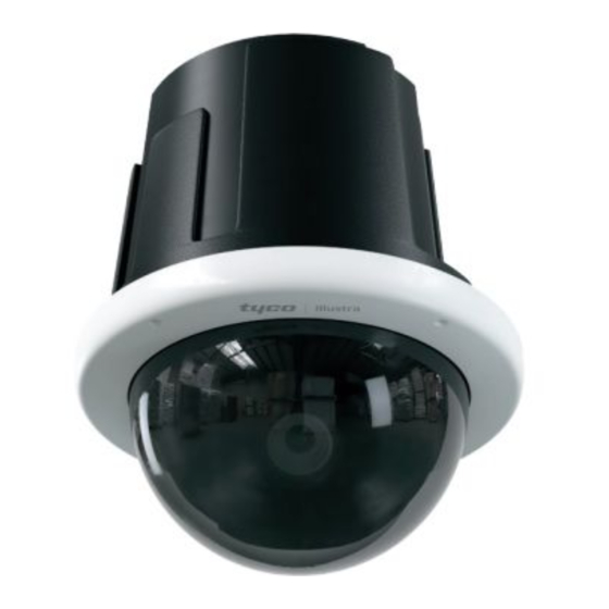
Figure 1: PG4 IR PTZ camera parts
Figure 1
Table 1: Camera part descriptions
Number
Security
1
2
3
4
Quick reference
Default IP: 192.168.1.168 (DHCP enabled)
Default Username / Password: admin / admin
Power: 802.3at PoE+ Type 2 (30w) or AC 24V
Note: As part of the start-up sequence the camera runs motor calibration, this
includes a 15 second 'shake' procedure.
Removing the camera from the Recessed camera housing
You can then access the cameras interior buttons and connections.
1.
Place the Recessed camera housing on a flat surface so that the Bubble
assembly (4) (Figure 1) is facing upward. Note: The four Bubble assembly
screws are now visible.
2.
Use the Torx security L-Key to loosen the four screws (2) (Figure 1) on the
camera Bubble assembly and remove the Bubble assembly. Note: As a
safety precaution the Bubble assembly is attached to a safety wire. The
camera lens (3) (Figure 1) is now visible.
3.
Loosen the three captive fastener screws (1) (Figure 2) on the camera.
4.
Gently push the two plastic clips (2) (Figure 2) located on the Recessed
camera housing away from the camera and lift the camera away from
Recessed camera housing.
Removing the camera from the Recessed camera housing
(continued)
Note: The camera interior buttons are located on the flat underside of the
camera. See Table 2 for all symbols and descriptions.
Description
Recessed camera housing
Bubble assembly screws (x4)
Camera lens
Bubble assembly
Figure 2
Table 2: Camera interior buttons / connections descriptions
Buttons / Connectors
AC24V Power connector
PoE Ethernet port
Audio and Alarm pins
(See Figure 3 for descriptions)
Reset to factory default (Hold for 5 seconds
and then release)
Power LED indicator
Reboots the camera
Figure 3: Audio and alarm pin descriptions
Figure 3
Mounting the camera
Refer to the Illustra mounting accessories webpage
https://www.illustracameras.com/products/accessories/mounts
The following mount accessory part numbers are applicable with the Illustra Pro
Gen4 Indoor 2MP and 8MP IR PTZ camera: RHOSW, RHOLW, RHOTR,
ROTRF, RHOWCA, ROENDC and IAPN-P-IS12-0.
Description
Analog out port
for assistance.
Advertisement
Table of Contents

Related Manuals for Johnson Controls TYCO Illustra Pro IPS02-P07-RT04


Summary of Contents for Johnson Controls TYCO Illustra Pro IPS02-P07-RT04
- Page 1 Table 1: Camera part descriptions Table 2: Camera interior buttons / connections descriptions Buttons / Connectors Description Number Description Security Recessed camera housing AC24V Power connector Quick Start Guide Bubble assembly screws (x4) (8200-2007-05_B0) Camera lens PoE Ethernet port Illustra Pro Gen4 2MP & 8MP IR PTZ Indoor camera Bubble assembly (P/N IPS02-P07-RT04 &...
- Page 2 Ensure that the two metal ‘clips’ on the camera align with the two plastic ‘tracks’ in the camera housing. © 2021 Johnson Controls. All rights reserved. JOHNSON CONTROLS, TYCO and Push the camera (1) (Figure 6) into the camera housing (2) (Figure 6) until it ILLUSTRA are trademarks and/or registered trademarks.
Need help?
Do you have a question about the TYCO Illustra Pro IPS02-P07-RT04 and is the answer not in the manual?
Questions and answers