Table of Contents
Advertisement
Quick Links
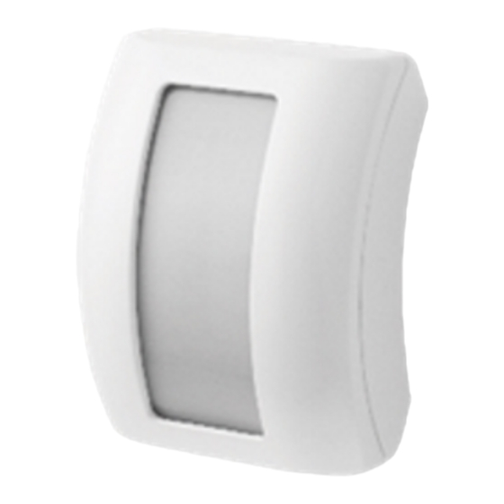
PIR Motion Sensor (IRC-29)
The PIR detects infrared signature to pick up movements within an assigned area and signals the Control Panel to activate the alarm if an
intruder crosses its' path of detection.
The PIR consists of a two-part design made up of a cover and a base. The cover contains all the electronics and optics and the base provides a
means for fixing. The base has knockouts to allow mounting on a flat surface or on the ceiling.
The PIR has a tamper switch which will be activated when the cover is opened, or when it is removed from the mounted surface. It can also alert
you to signal communication problems and low battery situations.
Identifying the Parts
1. PIR Lens
2. LED Indicator
The LED indicator is inside the front cover and only visible when activated.
3. Battery Compartment
The PIR uses 1 x CR123A (3V) Battery as power source.
4. Tamper Switch
The Tamper switch protects the PIR from unauthorized cover opening or
mounting surface removal.
5. Learn / Test Button
The test button is used for testing the radio performance and for learning purpose.
6
Sensitivity Increaser Jumper Switch (JP3)
.
- If the jumper is OFF (if the jumper link is removed or "parked" on one pin), the PIR's detection
sensitivity is in normal level. (Factory default)
- If the jumper is ON, the PIRs detection sensitivity is high.
7. Battery Insulator
Sleep Timer
The PIR has a "sleep time" of approximately 1 minute to conserve power. After transmitting a detected
movement, the PIR will not retransmit for 1 minute; any further movement detected during this sleep period
will extend the sleep time by another minute. In this way continuous movement in front of a PIR will not
unduly exhaust the battery.
Supervision Function
The PIR conducts a Self-test Periodically by transmitting a supervisory signal once every 15 to 18 minutes.
If the Control Panel fails to receive the Supervisory signals transmitted from a certain PIR for a preset time, an "Out-Of-Order" fault
message will be generated.
Sensitivity Adjustment
You can use the sensitivity increaser function to increase the PIR's detection sensitivity. To increase detection sensitivity, connect the
Jumper Switch (JP3) to the ON position. To maintain normal detection sensitivity, disconnect the Jumper Switch (JP3) to the OFF position.
(Factory default)
Test Mode
The PIR can be put into Test mode by pressing the Test Button. In Test mode, it will disable the sleep timer and will enable the LED indicator
to flash every time a movement is detected. Every time the Test Button is pressed, the PIR will transmit a test signal to the Control Panel for
radio range test and enter the test mode for 3 mins. It will exit Test Mode automatically after 3 minutes and return to normal mode.
LED Indicator
In Normal operation mode, the LED Indicator will flash quickly in the following situations:
When movement is detected under low battery condition.
When the cover is opened / removed from mounting surface and the tamper switch is triggered.
When movement is detected if the Tamper condition persists.
When movement is detected under Test mode.
When the Test Button is pressed under tamper condition or if PIR is under low battery.
The LED will not flash if the PIR tamper and battery are normal and is not under test mode,
If the LED flashes to indicate signal transmission, it will flash twice rapidly upon receiving acknowledgement from panel.
Battery
The PIR uses one 3V CR123A battery as power source.
The PIR features low battery detection function. If low battery voltage is detected, a low battery signal will be sent to the Control
Panel along with regular signal transmissions for the Control Panel to display the status accordingly.
For each installation, the battery is installed in by the factory before shipment with an Insulator inserted. Remove insulator to
activate battery.
When changing batteries, after removing the old batteries, press the Tamper Switch twice to fully discharge before inserting new
batteries.
Getting Started
1
Advertisement
Table of Contents

Related Manuals for Climax Technology IRC-29


Summary of Contents for Climax Technology IRC-29
- Page 1 PIR Motion Sensor (IRC-29) The PIR detects infrared signature to pick up movements within an assigned area and signals the Control Panel to activate the alarm if an intruder crosses its’ path of detection. The PIR consists of a two-part design made up of a cover and a base. The cover contains all the electronics and optics and the base provides a means for fixing.
- Page 2 Pull out the battery insulator to activate battery. The LED indicator will flash for 30 seconds. (The PIR is warming up). During the warm up period, the PIR will not be activated. It is recommended that you stay away from the detection area during this time. After the warm up period is over, the LED will turn off and the PIR will be ready for operation.
- Page 3 Installation Decide on the location of the PIR if it is to be horizontal / vertical or ceiling mounted. After the installation site is selected, follow the steps described above to mount the PIR. Press the Test Button to enter Test Mode. Walk around the protected area noting when the LED lights up and check that the detection coverage is adequate.
- Page 4 Federal Communication Commission Interference Statement This equipment has been tested and found to comply with the limits for a Class B digital device, pursuant to Part 15 of the FCC Rules. These limits are designed to provide reasonable protection against harmful interference in a residential installation. This equipment generates, uses and can radiate radio frequency energy and, if not installed and used in accordance with the instructions, may cause harmful interference to radio communications.
Need help?
Do you have a question about the IRC-29 and is the answer not in the manual?
Questions and answers