Norgren VR10 Operation & Service Manual
With ethernet/ip interface
Hide thumbs
Also See for VR10:
- Installation & maintenance instruction (53 pages) ,
- Operation & service manual (44 pages) ,
- Operation & service manual (42 pages)
Table of Contents
Advertisement
Quick Links
Operation & Service Manual
VR10 / VR15
With EtherNet/IP Interface
Before starting work read these instructions.
This manual contains proprietary information. No part of this
publication may be reproduced, transcribed or transmitted
in any form without the written consent of the publisher.
Every effort has been made to ensure that the information
contained in this manual is accurate. All rights reserved.
Advertisement
Table of Contents

Related Manuals for Norgren VR10


Summary of Contents for Norgren VR10
- Page 1 Operation & Service Manual VR10 / VR15 With EtherNet/IP Interface Before starting work read these instructions. This manual contains proprietary information. No part of this publication may be reproduced, transcribed or transmitted in any form without the written consent of the publisher.
- Page 2 24-Mar-2021 This Operation & Service Manual makes no claims of being complete as it does not cover all variants of the VR10 / VR15 valve islands. Therefore, this document is subject to extensions or changes. Construction & Design is subject to change (A1743-OPM-EP / Rev.004)
-
Page 3: Table Of Contents
Operation & Service Manual VR10 / VR15 with EtherNet/IP Interface CONTENTS CONTENTS ........................3 ABOUT THIS DOCUMENTATION ................5 IMPORTANT HINTS ..................... 6 GROUNDING AND EQUIPOTENTIAL BONDING ..........6 ELECTRICAL COMPONENTS ..................7 EtherNet/IP PORT 1 & PORT 2 ................8 POWER SUPPLY CONNECTOR ................ - Page 4 Operation & Service Manual VR10 / VR15 with EtherNet/IP Interface CYCLE COUNTING DATA ACQUISITION ............41 CYCLE COUNTER RESETTING ................. 44 LED STATUS DESCRIPTION ..................48 TECHNICAL DATA EtherNet/IP INTERFACE ............49 CUSTOMER SUPPORT ..................... 50 Construction & Design is subject to change (A1743-OPM-EP / Rev.004)
-
Page 5: About This Documentation
Operation & Service Manual VR10 / VR15 with EtherNet/IP Interface ABOUT THIS DOCUMENTATION This User Guide contains the information to set up and operate VR10 / VR15 valve island with EtherNet/IP Interface and to detect and resolve problems. Note: In addition to the specific information for the EtherNet/IP variants, all data sheets and VR10 / VR15 PROTOCOL / MULTIPOLE SERIES IP65 VERSION Operation &... -
Page 6: Important Hints
Operation & Service Manual VR10 / VR15 with EtherNet/IP Interface IMPORTANT HINTS GROUNDING AND EQUIPOTENTIAL BONDING Proper grounding and equipotential bonding are very important to protect against electromagnetic interferences in EtherNet/IP networks. To reduce potential impact, grounding of the EtherNet/IP cable screen should be done at both ends of every cable (i.e. -
Page 7: Electrical Components
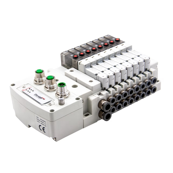
Operation & Service Manual VR10 / VR15 with EtherNet/IP Interface ELECTRICAL COMPONENTS 1- Port 1 for EtherNet/IP (M12 x 1 | Female | 4 – pin | D – coded) 2- Port 2 for Ethernet/IP (M12 x 1 | Female | 4 – pin | D – coded) 3- PWR: Power supply connector (M12 x 1 | Male | 5 –... -
Page 8: Ethernet/Ip Port 1 & Port 2
Operation & Service Manual VR10 / VR15 with EtherNet/IP Interface EtherNet/IP PORT 1 & PORT 2 M12 / 4 pins / Female Connector / D-coded Pin No. Function Transmission Data + (TD +) Receive Data + (RD +) Transmission Data - (TD -) -
Page 9: Electrical Data
Operation & Service Manual VR10 / VR15 with EtherNet/IP Interface ELECTRICAL DATA Specification Remark Valve voltage range (VA) 24VDC +10%/-5% PELV Electronics voltage range (VB) 24VDC +/-10% PELV VA: n × 40 mA Maximum currents n = number of solenoids VB: <... -
Page 10: Solenoid Number, Output Point & Valve Station Mapping
Operation & Service Manual VR10 / VR15 with EtherNet/IP Interface SOLENOID NUMBER, OUTPUT POINT & VALVE STATION MAPPING MAPPING RULES FOR VALVE STATIONS £ 12 § If valve stations ≤ 12, 2 solenoid numbers are always reserved for each valve station. *... -
Page 11: Commissioning
NORGREN and can be downloaded from the following web link: § https://www.norgren.com/uk/en/technical-support/software The EDS (Electronic Data Sheet) file could be used for all variants VR10 / VR15: § “NORGREN-VR1X-EP-Vxx-JJJJMMDD.eds” Note: “JJJJMMDD” (JJJJ-year, MM-month, DD-day) is date of release, “Vxx” (xx-version number) is version of release. - Page 12 Operation & Service Manual VR10 / VR15 with EtherNet/IP Interface § In next window, click on “Register a single file”. (Tag 3) § “Browse” to the source path where EDS file is stored, then click on “Next”. (Tag 4-5) §...
- Page 13 Operation & Service Manual VR10 / VR15 with EtherNet/IP Interface § Click “Next” by accepting the default icon of Norgren valve island. (Tag 7) § Click “Next” on the task summary window. (Tag 8) § Click Finish. (Tag 9) §...
-
Page 14: Hardware Configuration
Operation & Service Manual VR10 / VR15 with EtherNet/IP Interface HARDWARE CONFIGURATION Note: please create a new project or open an existing project before configuring any hardware. Please make sure the EtherNet/IP module has been configured correctly before add valve island moudle in the “Controller Organizer”... - Page 15 Operation & Service Manual VR10 / VR15 with EtherNet/IP Interface § In the “New Module” window, select “General” tab, input Name and IP address. (Tag 7-8) § Select “Connection” tab. (Tag 9) Set “Requested Packet Interval (RPI)” § greater than or equal to 10ms. The RPI times has a direct impact to the busload.
-
Page 16: Assign Ip Address To Valve Island
VR10 / VR15 with EtherNet/IP Interface 6.2.2 Assign IP Address to Valve Island VR10/VR15 provides several options to assign IP address to valve island by removing the window to set the rotary and DIP switch with a 2mm slotted screwdriver during power off. -
Page 17: Ip Address Setting By Remote Control
§ IP address set by DHCP Server VR10/VR15 is set as a DHCP client in remote control mode by default. IP Address must be assigned using a DHCP server or a similar tool. The IP address must be set again after each power cycle. - Page 18 Operation & Service Manual VR10 / VR15 with EtherNet/IP Interface § Static IP Address assignment Static IP address must be done once and is valid after power cycles. The following example shows how to set static IP address by Rockwell Automation tool BOOTP/DHCP.
- Page 19 Operation & Service Manual VR10 / VR15 with EtherNet/IP Interface • “[Disable DHCP] command successful” will appear in the Errors and warnings status. Construction & Design is subject to change (A1743-OPM-EP / Rev.004)
- Page 20 Operation & Service Manual VR10 / VR15 with EtherNet/IP Interface § Static IP address can also set by TCP/IP Interface Object. The Read/Write access to the TCP/IP Interface Object is done via the Explicit Messages communication method. The configuration method is set up with the bits0-3 in attribute 3. Please use the statically assigned IP configuration set up value “0”...
-
Page 21: Ip Address Set By Dial Panels
Operation & Service Manual VR10 / VR15 with EtherNet/IP Interface Next table shows the structure of the interface configuration attribute. Attribute STRUCT of: Interface Configuration UDSINT IP Address UDSINT Network Mask UDSINT Gateway Address UDSINT Name Server UDSINT Name Server 2... -
Page 22: Digital Outputs Data
In EDS file, the digital outputs data is defined as “Assembly Object Instance: 150d, Class: 0x04”. § VR10 / VR15 valve island channel outputs will be real-time monitored & displayed. § Channel outputs process codes will be reported by “Output Byte 0”, “Output Byte 1” and “Output Byte 2”. - Page 23 Operation & Service Manual VR10 / VR15 with EtherNet/IP Interface § Outputs Value and solenoid number mapping relationships are shown in table below. • The bit is “1” means there is output occurred on that solenoid. • The bit is “0” means no output.
-
Page 24: Digital Inputs Data
Operation & Service Manual VR10 / VR15 with EtherNet/IP Interface DIGITAL INPUTS DATA In EDS file, the digital inputs data is defined as “Assembly Object Instance: 100d, Class: 0x04”. The digital inputs data reflect diagnostic status, it includes 4 parts:... - Page 25 Operation & Service Manual VR10 / VR15 with EtherNet/IP Interface § The diagnostic status and digital inputs data mapping shows in following table: Input Byte 0 Overall status Fault type UV-VB OV-VB UV-VA OV-VA diagnostics Bit 7 Bit 6 Bit 5...
-
Page 26: Overall Status Diagnostics
VR10 / VR15 with EtherNet/IP Interface 6.4.1 Overall Status Diagnostics § VR10 / VR15 valve island module status will be shown in real-time. § The overall status diagnostic includes: • Over voltage diagnostics for valve power • Under voltage diagnostics for valve power •... - Page 27 Operation & Service Manual VR10 / VR15 with EtherNet/IP Interface § Common fault errors are shown below: Fault type Associated LED & Remark Over voltage diagnostics for valve power “VA” LED, red Abbreviation: OV-VA Under voltage diagnostics for valve power “VA”...
-
Page 28: Short Circuit Diagnostics
Operation & Service Manual VR10 / VR15 with EtherNet/IP Interface 6.4.2 Short Circuit Diagnostics § Short circuit fault error codes will be reported by “Input Byte 1”, “Input Byte 2” and “Input Byte 3”. Construction & Design is subject to change (A1743-OPM-EP / Rev.004) - Page 29 Operation & Service Manual VR10 / VR15 with EtherNet/IP Interface § Binary value and solenoid number mapping relationships are shown in table below. 0 is no fault, 1 is fault found. Input Byte 1 Solenoid Sol.08 Sol.07 Sol.06 Sol.05 Sol.04 Sol.03...
-
Page 30: Open Load Diagnostics
Operation & Service Manual VR10 / VR15 with EtherNet/IP Interface 6.4.3 Open Load Diagnostics § Open load fault error codes will be reported by “Input Byte 4”, “Input Byte 5” and “Input Byte 6”. Note: Need to enable open load diagnostics. - Page 31 Operation & Service Manual VR10 / VR15 with EtherNet/IP Interface § Binary value and solenoid number mapping relationships are shown in table below. 0 is no fault, 1 is fault found. Input Byte 4 Solenoid Sol.08 Sol.07 Sol.06 Sol.05 Sol.04 Sol.03...
-
Page 32: Cycle Overrun Diagnostics
Operation & Service Manual VR10 / VR15 with EtherNet/IP Interface 6.4.4 Cycle Overrun Diagnostics Cycle overrun fault error codes will be reported by “Input Byte 7”, “Input Byte 8” and “Input § Byte 9”. Note: Need to set valid count limit so that this diagnostic function is effective. - Page 33 Operation & Service Manual VR10 / VR15 with EtherNet/IP Interface § Binary value and solenoid number mapping relationships are shown in table below. 0 is no fault, 1 is fault found. Input Byte 7 Solenoid Sol.08 Sol.07 Sol.06 Sol.05 Sol.04 Sol.03...
-
Page 34: Parameterization
0x04”. All the parameterization data must be downloaded after setting. 6.5.1 Cycle Counter Limit It is possible for VR10 / VR15 valve island to set cycle counter limit for each solenoid. If count exceeds limit, MS LED on the valve island will change from green to flashing red. - Page 35 Operation & Service Manual VR10 / VR15 with EtherNet/IP Interface § Variable name and solenoid number mapping relation is shown in table below. § The range of counter limit for each solenoid between 16#0000_0000 and 16#ffff_ ffff. Solenoid number and output point mapping relationships are shown in Chapter 5.
-
Page 36: Open Load Diagnostics Setting
VR10 / VR15 with EtherNet/IP Interface 6.5.2 Open Load Diagnostics Setting It is possible for VR10 / VR15 valve island to enable / disable the open load diagnostics for each solenoid. If disabled, no EtherNet/IP open load diagnostic error appears. Otherwise MS LED on the valve island change from green to red flashing. - Page 37 Operation & Service Manual VR10 / VR15 with EtherNet/IP Interface § Value and solenoid number mapping relationships are shown in table below. § The bit that is set to “1” means enable open load diagnostics function of that solenoid. The bit that is set to “0” means disable open load diagnostics function of that solenoid.
-
Page 38: Fail Safe State Setting
Operation & Service Manual VR10 / VR15 with EtherNet/IP Interface 6.5.3 Fail Safe State Setting It is possible to define the behaviour of the outputs in case of broken EtherNet/IP communication or PLC stopped. § Click “Control Tags”. (Tag 1) §... - Page 39 Operation & Service Manual VR10 / VR15 with EtherNet/IP Interface § Value and solenoid number mapping relationships are shown in table below. § The bit that is set to “1” means last valid value of that solenoid is retained in case of broken EtherNet/IP communication or PLC stopped.
-
Page 40: Voltage And Short Circuit Diagnostics
VR10 / VR15 with EtherNet/IP Interface 6.5.4 Voltage and Short Circuit Diagnostics VR10 / VR15 valve island supports voltage diagnostics for both electronic power and valve power and short circuit diagnostics for each solenoid. These two diagnostic functions cannot be disabled. -
Page 41: Cycle Counting Data Acquisition
VR10 / VR15 valve island supports cycle counting for each solenoid. § Cycle counting data can be obtained by ladder Element “MSG”. The following steps give a brief instruction of using “MSG” to get data from VR10/VR15. § § In the message configuration of “MSG”. (Tag 1) §... - Page 42 Operation & Service Manual VR10 / VR15 with EtherNet/IP Interface Select “Communication” Tab. § (Tag 9) § Click “Browse” button. (Tag 10) § Select the valve island module and click OK. (Tag 11-12) Construction & Design is subject to change (A1743-OPM-EP / Rev.004)
- Page 43 Operation & Service Manual VR10 / VR15 with EtherNet/IP Interface § Add an “Examine On” element connect to “MSG” element. (Tag 13) Download the program to PLC and set PLC to Run Mode, then every time getting a rising §...
-
Page 44: Cycle Counter Resetting
CYCLE COUNTER RESETTING In EDS file, cycle counter resetting data is defined as “Assembly Object Instance: 102d, Class: 0x04”. VR10 / VR15 valve island supports counter reset for each solenoid. Cycle counter data can be reset by ladder Element “MSG”. §... - Page 45 Operation & Service Manual VR10 / VR15 with EtherNet/IP Interface § Set “Source Length” Value 3. (Tag 9) § Select “Communication” Tab. (Tag 10) § Click “Browse” button. (Tag 11) § Select the valve island module and click OK. (Tag 12-13)
- Page 46 Operation & Service Manual VR10 / VR15 with EtherNet/IP Interface § Expand variable created for counter reset, set value to “1” or “0” as required. All bits are set to “0” as default. (Tag 14-15) Construction & Design is subject to change (A1743-OPM-EP / Rev.004)
- Page 47 Operation & Service Manual VR10 / VR15 with EtherNet/IP Interface § Value and solenoid number mapping relationships are shown in the table below. § The bit that is set to “1” means to clear & reset cycle counting value of that solenoid.
-
Page 48: Led Status Description
Operation & Service Manual VR10 / VR15 with EtherNet/IP Interface LED STATUS DESCRIPTION Symbol LED Status Description No IP address or no power Green on Connected Flashing green Not Connected Flashing red Connection Timeout No power Green on Device Operational... -
Page 49: Technical Data Ethernet/Ip Interface
Operation & Service Manual VR10 / VR15 with EtherNet/IP Interface TECHNICAL DATA EtherNet/IP INTERFACE Specification Remark Number of ports Link Speed 100Mbit/s Duplex Mode Full Duplex DLR Mode Supported Device Level Ring EtherNet/IP (ODVA Compliant to IEC61158 Certification) IP Address modes... -
Page 50: Customer Support
© This document, as well as the data, specifications and other information presented in it are the sole property of Norgren. It may not be reproduced or given to third parties without their consent. Subject to change without notice. - Page 51 50 countries, as well as manufacturing capability in Brazil, China, Czech Republic, Germany, India, Mexico UK and the USA. For information on all Norgren companies visit www.norgren.com Supported by distributors worldwide. Norgren, Buschjost, FAS, Herion,...
Need help?
Do you have a question about the VR10 and is the answer not in the manual?
Questions and answers