Norgren VR10 Operation & Service Manual
With profinet interface
Hide thumbs
Also See for VR10:
- Installation & maintenance instruction (53 pages) ,
- Operation & service manual (51 pages) ,
- Operation & service manual (44 pages)
Table of Contents
Advertisement
Quick Links
Advertisement
Table of Contents

Subscribe to Our Youtube Channel
Related Manuals for Norgren VR10


Summary of Contents for Norgren VR10
- Page 1 VR10 / VR15 With PROFINET Interface Operation & Service Manual...
- Page 2 5-April-2021 This Operation & Service Manual makes no claims of being complete as it does not cover all variants of the VR10 / VR15 valve manifolds. Therefore, this document is subject to extensions or changes. Construction & Design is subject to change (A1743-OPM-PN / Rev1)
-
Page 3: Table Of Contents
Operation & Service Manual VR10 / VR15 with PROFINET Interface CONTENTS CONTENTS ........................3 ABOUT THIS DOCUMENTATION.................. 5 IMPORTANT HINTS ....................... 6 GROUNDING AND EQUIPOTENTIAL BONDING........... 6 ELECTRICAL FEATURES ....................7 PROFINET PORT 1 & PORT 2 ................8 POWER SUPPLY CONNECTOR ................8 ELECTRICAL DATA.................... - Page 4 Operation & Service Manual VR10 / VR15 with PROFINET Interface 7.3.2 Open Load Diagnostics ..................31 7.3.3 Cycle Overrun Diagnostics ................34 DIAGNOSTICS & OUTPUTS MAPPING OBJECT ............37 LED STATUS DESCRIPTION ..................39 10 PROFINET ERROR CODES ..................40 11 TECHNICAL DATA PROFINET INTERFACE ..............
-
Page 5: About This Documentation
Operation & Service Manual VR10 / VR15 with PROFINET Interface ABOUT THIS DOCUMENTATION This User Guide contains the information to set up and operate VR10 / VR15 valve manifold with PROFINET Interface and to detect and resolve problems. Note: In addition to the specific information for the PROFINET variants, all data sheets and VR10 / VR15 PROTOCOL / MULTIPOLE SERIES IP65 VERSION Operation &... -
Page 6: Important Hints
Operation & Service Manual VR10 / VR15 with PROFINET Interface IMPORTANT HINTS GROUNDING AND EQUIPOTENTIAL BONDING Proper grounding and equipotential bonding are very important to protect against electromagnetic interferences in PROFINET networks. In order to reduce potential impact, grounding of the PROFINET cable screen should be done at both ends of every cable (i.e. -
Page 7: Electrical Features
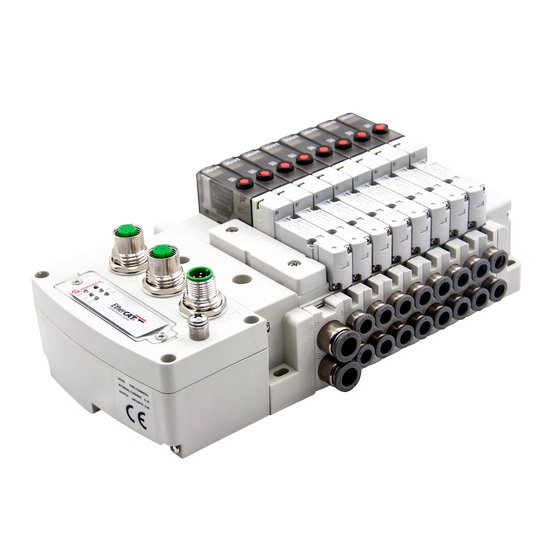
Operation & Service Manual VR10 / VR15 with PROFINET Interface ELECTRICAL FEATURES 1- Port 1 for PROFINET (M12 x 1 | Female | 4 – pin | D – coded) 2- Port 2 for PROFINET (M12 x 1 | Female | 4 – pin | D – coded) 3- PWR: Power Supply (M12 x 1 | Male | 5 –... -
Page 8: Profinet Port 1 & Port 2
Operation & Service Manual VR10 / VR15 with PROFINET Interface PROFINET PORT 1 & PORT 2 M12 / 4 pins / Female Connector / D-coded Pin No. Function Transmission Data + (TD +) Receive Data + (RD +) Transmission Data - (TD -) -
Page 9: Electrical Data
Operation & Service Manual VR10 / VR15 with PROFINET Interface ELECTRICAL DATA Specification Remark Valve voltage range (VA) 24VDC +10%/-5% PELV Electronics voltage range (VB) 24VDC +/-10% PELV VA: n × 40 mA Maximum currents n = number of solenoids VB: ... -
Page 10: Solenoid Number, Output Point & Valve Station Mapping
Operation & Service Manual VR10 / VR15 with PROFINET Interface SOLENOID NUMBER, OUTPUT POINT & VALVE STATION MAPPING MAPPING RULES FOR VALVE STATIONS 12 If valve stations ≤ 12, 2 solenoid numbers are always reserved for each valve station.*... -
Page 11: Commissioning
Click “Options” -> “Manage general station description files (GSD)”. Select source path where GSDML file is stored, tick the GSDML file and install. The GSDML file is provided by Norgren and can be downloaded from the following web link: https://www.norgren.com/us/en/technical-support/software... -
Page 12: Hardware Configuration
Operation & Service Manual VR10 / VR15 with PROFINET Interface HARDWARE CONFIGURATION After the successful installation of the GSDML file the VR10 / VR15 is listed in the hardware catalog. Construction & Design is subject to change (A1743-OPM-PN / Rev1) -
Page 13: Add Valve Manifold
VR10 / VR15 with PROFINET Interface 6.2.1 Add Valve Manifold Expand “Other field devices” -> “PROFINET IO” -> “Valves” -> “Norgren Manufacturing Co., Ltd.” and find “VR1X-PN MRP” listed here. (Tag 1-2) Double click or drag “VR1X-PN MRP” to drop it into Network view. (Tag 3) Assign PLC to the valve manifold by clicking “Not assigned”... - Page 14 Operation & Service Manual VR10 / VR15 with PROFINET Interface Double click the added valve island in Network view to switch to Device view. (Tag 5) Expand “Module” then double click “VR1X-PN with 10 bytes Input” module and “VR1X-PN with 3 bytes Output” module in hardware catalogue. (Tag 6) 10 bytes Input are used for diagnostics, from input byte 0 to input byte 9.
-
Page 15: Identifying Valve Manifolds In Network
Operation & Service Manual VR10 / VR15 with PROFINET Interface 6.2.2 Identifying Valve Manifolds in Network Blink Test • Blinking BF LED can help to identify valve manifolds in the network. • Select the valve manifold you want to identify then tick “Flash LED” in the left pane. -
Page 16: Parameterization
PARAMETERIZATION 6.3.1 Open Load Diagnostics Setting It is possible for VR10 / VR15 valve manifold to enable / disable the open load diagnostics for each solenoid. If disabled, no PROFINET open load diagnostic error appears. Otherwise a PROFINET channel diagnostic with error description and channel number appears and SF LED on the valve manifold change color from green to red color. -
Page 17: Fail Safe State Setting
Operation & Service Manual VR10 / VR15 with PROFINET Interface 6.3.2 Fail Safe State Setting It is possible to define the behaviour of the outputs in case of broken PROFINET communication or “IOPS = Bad” (PLC stopped). The following two states could be defined by the outputs: 1) Output —... -
Page 18: Voltage And Short Circuit Diagnostics
VR10 / VR15 with PROFINET Interface 6.3.3 Voltage and Short Circuit Diagnostics VR10 / VR15 valve manifold supports voltage diagnostics for both electronic power and valve power and short circuit diagnostics for each solenoid. And these two diagnostic functions cannot be disabled. -
Page 19: Cycle Counter Setting
VR10 / VR15 with PROFINET Interface 6.3.4 Cycle Counter Setting VR10 / VR15 valve manifold supports cycle counting, count limit set, and counter reset for each solenoid. Cycle counting and counter reset can be achieved by programming. Count limit set •... -
Page 20: Go Online And Monitor Data
Operation & Service Manual VR10 / VR15 with PROFINET Interface GO ONLINE AND MONITOR DATA 6.4.1 Compiling and Download After finished configuration, compile the project, and download it to PROFINET controller (PLC). 6.4.2 Cycle Counting Data Acquisition Monitor the “96-byte data array”, the cycle counting data will be displayed after each byte in “Monitor value”... - Page 21 Operation & Service Manual VR10 / VR15 with PROFINET Interface Always 4 adjacent bytes are allocated to each solenoid, 96 bytes will assign to 24 solenoids, from Sol.01 to Sol.24. Detailed allocation is shown as below: …… Solenoid Sol.01 Sol.03 Sol.05...
-
Page 22: Cycle Counter Resetting
Operation & Service Manual VR10 / VR15 with PROFINET Interface 6.4.3 Cycle Counter Resetting Input specific binary code in “Modify value” for the “3-byte data array”. (Tag 1) Be cautioned that must input correct binary codes for each solenoid & each byte before executing following reset step, otherwise the cycle counting data will be erased improperly. -
Page 23: Diagnostics
Operation & Service Manual VR10 / VR15 with PROFINET Interface DIAGNOSTICS DIAGNOSTICS INFORMATION PORTAL Click “Go online” button to make PLC, valve manifold and PC online. When error alarm symbol appears, double click the failed valve manifold in Network view to switch to Device view. - Page 24 Operation & Service Manual VR10 / VR15 with PROFINET Interface Click “Diagnostic status” in diagnostics window to find the valve manifold module error details. (Tag 3) Click “Channel diagnostics” in diagnostics window to find each solenoid error details. (Tag 4)
-
Page 25: Overall Status Diagnostics
Operation & Service Manual VR10 / VR15 with PROFINET Interface OVERALL STATUS DIAGNOSTICS VR10 / VR15 valve manifold module status will be shown in real-time. The diagnostic module status includes: • Over voltage diagnostics for valve power • Under voltage diagnostics for valve power •... - Page 26 Operation & Service Manual VR10 / VR15 with PROFINET Interface Fault error codes will be reported by “Input Byte 0”. Fault error codes are displayed in hexadecimal. Common fault error codes are shown below: Fault type Error code Associated LED & Remark Over voltage diagnostics for valve power “VA”...
-
Page 27: Channel Diagnostics
Operation & Service Manual VR10 / VR15 with PROFINET Interface CHANNEL DIAGNOSTICS VR10 / VR15 valve manifold channel status will be shown in real-time. The diagnostic channel status includes: • Short circuit diagnostics per solenoid • Open load diagnostics per solenoid (e.g. wire break of solenoid) •... -
Page 28: Short Circuit Diagnostics
Operation & Service Manual VR10 / VR15 with PROFINET Interface 7.3.1 Short Circuit Diagnostics TIA Portal channel diagnostics will alarm short circuit like following capture and the error description will be here: Construction & Design is subject to change (A1743-OPM-PN / Rev1) - Page 29 Operation & Service Manual VR10 / VR15 with PROFINET Interface Short circuit fault error codes will be reported by “Input Byte 1”, “Input Byte 2” and “Input Byte 3”. Fault error codes are displayed in hexadecimal. Common short circuit fault error codes are shown in table:...
- Page 30 Operation & Service Manual VR10 / VR15 with PROFINET Interface Binary code and solenoid number mapping relation is shown in table below. 0 is no fault, 1 is fault found. Input Byte 1 Solenoid Sol.08 Sol.07 Sol.06 Sol.05 Sol.04 Sol.03 Sol.02...
-
Page 31: Open Load Diagnostics
Operation & Service Manual VR10 / VR15 with PROFINET Interface 7.3.2 Open Load Diagnostics TIA Portal channel diagnostics will alarm open load like following capture and the error description will be here: Construction & Design is subject to change (A1743-OPM-PN / Rev1) - Page 32 Operation & Service Manual VR10 / VR15 with PROFINET Interface Open load fault error codes will be reported by “Input Byte 4”, “Input Byte 5” and “Input Byte 6”. Fault error codes are displayed in hexadecimal. Need to enable open load diagnostics.
- Page 33 Operation & Service Manual VR10 / VR15 with PROFINET Interface Binary code and solenoid number mapping relation is shown in table below. 0 is no fault, 1 is fault found. Input Byte 4 Solenoid Sol.08 Sol.07 Sol.06 Sol.05 Sol.04 Sol.03 Sol.02...
-
Page 34: Cycle Overrun Diagnostics
Operation & Service Manual VR10 / VR15 with PROFINET Interface 7.3.3 Cycle Overrun Diagnostics TIA Portal channel diagnostics will alarm cycle overrun like following capture and the error description will be here: Construction & Design is subject to change (A1743-OPM-PN / Rev1) - Page 35 Operation & Service Manual VR10 / VR15 with PROFINET Interface Cycle overrun fault error codes will be reported by “Input Byte 7”, “Input Byte 8” and “Input Byte 9”. Fault error codes are displayed in hexadecimal. Need to set valid count limit so that this diagnostic function is effective.
- Page 36 Operation & Service Manual VR10 / VR15 with PROFINET Interface Binary code and solenoid number mapping relation is shown in table below. 0 is no fault, 1 is fault found. Input Byte 7 Solenoid Sol.08 Sol.07 Sol.06 Sol.05 Sol.04 Sol.03 Sol.02...
-
Page 37: Diagnostics & Outputs Mapping Object
Operation & Service Manual VR10 / VR15 with PROFINET Interface DIAGNOSTICS & OUTPUTS MAPPING OBJECT Programming languages comply with IEC 61131-3:2013. Input Byte 0 Overall status Fault type UV-VB OV-VB UV-VA OV-VA diagnostics Bit 7 Bit 6 Bit 5 Bit 4... - Page 38 Operation & Service Manual VR10 / VR15 with PROFINET Interface Output Byte 0 Solenoid Sol.08 Sol.07 Sol.06 Sol.05 Sol.04 Sol.03 Sol.02 Sol.01 Bit 7 Bit 6 Bit 5 Bit 4 Bit 3 Bit 2 Bit 1 Bit 0 Output Byte 1 Solenoid Sol.16...
-
Page 39: Led Status Description
Operation & Service Manual VR10 / VR15 with PROFINET Interface LED STATUS DESCRIPTION Symbol LED Status Description PROFINET Software is not initialized Red on Device is offline Hardware configuration and Flashing red parameterization is not plausible Triple flashing red IOPS = BAD (PLC stopped) -
Page 40: Profinet Error Codes
Operation & Service Manual VR10 / VR15 with PROFINET Interface PROFINET ERROR CODES Error code Error description Associated LED (Hexadecimal) “SF” LED, green 0×00 OK, no errors “SF” LED, quickly flashing red 0×01 Solenoid, short circuit “SF” LED, slowly flashing red 0×06... -
Page 41: Technical Data Profinet Interface
Operation & Service Manual VR10 / VR15 with PROFINET Interface TECHNICAL DATA PROFINET INTERFACE Specification Remark Number of ports Transfer speed 100Mbit/s Duplex mode Full Duplex RT mode Supported Real Time Protocol IRT mode Supported Isochronous Real Time Protocol Media Redundancy Protocol... -
Page 42: Customer Support
© This document, as well as the data, specifications and other information presented in it are the sole property of Norgren. It may not be reproduced or given to third parties without their consent. Subject to change without notice.
Need help?
Do you have a question about the VR10 and is the answer not in the manual?
Questions and answers