Norgren VR10 Operation & Service Manual
Hide thumbs
Also See for VR10:
- Installation & maintenance instruction (53 pages) ,
- Operation & service manual (51 pages) ,
- Operation & service manual (42 pages)
Table of Contents
Advertisement
Quick Links
Operation & Service Manual
VR10 / VR15
With IO-Link Interface
Before starting work read these instructions.
This manual contains proprietary information. No part of this
publication may be reproduced, transcribed or transmitted
in any form without the written consent of the publisher.
Every effort has been made to ensure that the information
contained in this manual is accurate. All rights reserved.
Advertisement
Table of Contents

Related Manuals for Norgren VR10


Summary of Contents for Norgren VR10
- Page 1 Operation & Service Manual VR10 / VR15 With IO-Link Interface Before starting work read these instructions. This manual contains proprietary information. No part of this publication may be reproduced, transcribed or transmitted in any form without the written consent of the publisher.
- Page 2 25-Jan-2021 This Operation & Service Manual makes no claims of being complete as it does not cover all variants of the VR10 / VR15 valve islands. Therefore, this document is subject to extensions or changes. Construction & Design is subject to change (A1743-OPM-IL / Rev.002)
-
Page 3: Table Of Contents
Operation & Service Manual VR10 / VR15 with IO-Link Interface CONTENTS CONTENTS ........................3 ABOUT THIS DOCUMENTATION ................5 IMPORTANT HINTS ..................... 6 GROUNDING AND EQUIPOTENTIAL BONDING ..........6 USING AN IO-LINK MASTER ................6 ELECTRICAL CONNECTIONS ..................7 IO-LINK CONNECTOR (PORT CLASS B) ............. 8 ELECTRICAL DATA .................... - Page 4 Operation & Service Manual VR10 / VR15 with IO-Link Interface OVERALL STATUS DIAGNOSTICS ..............26 SOLENOID STATUS DIAGNOSTICS ..............29 8.3.1 Short Circuit Diagnostics ................29 8.3.2 Open Load Diagnostics .................. 32 8.3.3 Cycle Overrun Diagnostics ................35 DIAGNOSTICS & OUTPUTS MAPPING OBJECT ............. 38 10 LED INDICATION AND BAUD RATE SETTING ............
-
Page 5: About This Documentation
Link Interface and to detect and resolve problems. Note: In addition to the specific information for the IO-Link variants, all data sheets and VR10 / VR15 PROTOCOL / MULTIPOLE SERIES IP65 VERSION Operation & Service Manual are applicable and remain valid. -
Page 6: Important Hints
0.75mm USING AN IO-LINK MASTER It is recommended to use an IO-Link master with port Class B to control VR10 / VR15 IO-Link valve islands. The signal wire and valve power supply wire can be connected via this 5-wire unshielded cable. -
Page 7: Electrical Connections
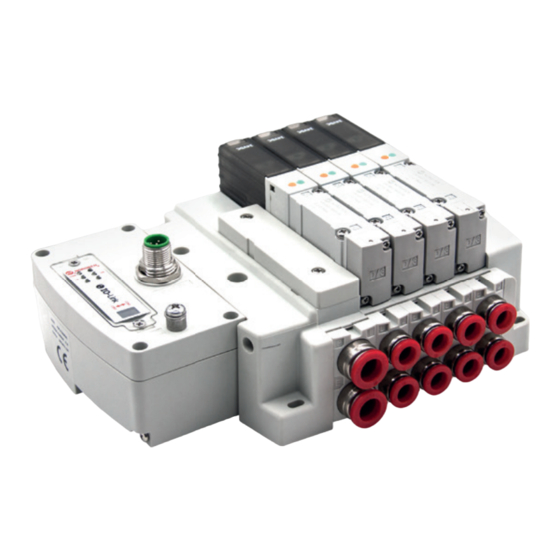
Operation & Service Manual VR10 / VR15 with IO-Link Interface ELECTRICAL CONNECTIONS 1- IO-Link connector (Port Class B) (M12 x 1 | Male | 5 – pin | A – coded) 2- Status LEDs 3- Valve status LEDs 4- Earth screw (M4) 5- Baud rate setting switch (COM2 &... -
Page 8: Io-Link Connector (Port Class B)
Operation & Service Manual VR10 / VR15 with IO-Link Interface IO-LINK CONNECTOR (PORT CLASS B) Pin allocating of IO-Link connector § M12 / 5 pins / Male Connector / A-coded / Class B Pin No. Function L+ (VB +) 24V electronics power supply... -
Page 9: Solenoid Number & Valve Station Mapping
Operation & Service Manual VR10 / VR15 with IO-Link Interface SOLENOID NUMBER & VALVE STATION MAPPING MAPPING RULES FOR VALVE STATIONS £ 12 § If valve stations ≤ 12, 2 solenoid numbers are always reserved for each valve station. *... -
Page 10: Commissioning
USB IO-Link master e.g. TMGTE IO-Link Device Tool can be used in conjunction with respective software for IODD files and visual & graphical setting, or consult NORGREN directly. All examples in this document are made with Siemens IO-Link master ET 200eco PN with PROFINET interface / Port Class B and the configuration software SIMATIC S7-PCT Version 3.5 SP1. - Page 11 Click “Options” -> “Import IODD…”. § Select source path where IODD file is stored, tick the IODD file and import. The IODD files are provided by NORGREN and can be downloaded from the following web link: § https://www.norgren.com/uk/en/technical-support/software Construction & Design is subject to change (A1743-OPM-IL / Rev.002)
- Page 12 Operation & Service Manual VR10 / VR15 with IO-Link Interface After the successful installation of the IODD file, the VR10 / VR15 is listed in the hardware catalogue. Construction & Design is subject to change (A1743-OPM-IL / Rev.002)
-
Page 13: Configuration On Ports Of Io-Link Master
Operation & Service Manual VR10 / VR15 with IO-Link Interface CONFIGURATION ON PORTS OF IO-LINK MASTER 6.3.1 Submodules Configuration on Ports of IO-Link Master Before commissioning the valve island, the behaviour must be assigned to ports of IO-Link master. After the successfully adding the IO-Link master and configuring the network in TIA Portal, a submodule with at least 10 bytes of IO-Link input data and at least 3 bytes of IO-Link output data must be assigned to the associated port which the valve island is physically connected to. -
Page 14: Port Parameters Configuration
• Selecting option “IO-Link manual”: Activating parameter setting of the data storage function for the selected port. • Vendor ID: Manufacturer ID of connected IO-Link device, 1353 for VR10 / VR15. • Device ID: Device ID of connected IO-Link device, 1 for COM3, 2 for COM2. -
Page 15: Data Storage Function
VR10 / VR15 with IO-Link Interface DATA STORAGE FUNCTION Valve island VR10 / VR15 with IO-Link Interface supports data storage function. Make sure port parameters options are set as shown below to enable data storage function before replacing valve island. -
Page 16: Parameterization
Operation & Service Manual VR10 / VR15 with IO-Link Interface PARAMETERIZATION Note: Parameterization can be carried out via the web interface (webserver integrated with IO-Link master) or via configuration tools for IO-Link master. License could be required from IO-link master manufacture. - Page 17 Operation & Service Manual VR10 / VR15 with IO-Link Interface § Click “Load to PG with Devices” button to find devices online. § After successfully adding devices, the valve islands will appear at related port. Construction & Design is subject to change (A1743-OPM-IL / Rev.002)
-
Page 18: Open Load Diagnostics Setting
VR10 / VR15 with IO-Link Interface 6.5.2 Open Load Diagnostics Setting It is possible for VR10 / VR15 valve island to enable / disable the open load diagnostics for each solenoid. If disabled, no open load diagnostic error appears. Otherwise a status diagnostic and channel diagnostic with error description appears and SF LED on the IO-Link master change from green to red colour. -
Page 19: Voltage And Short Circuit Diagnostics
In case of short circuit, a status diagnostic and channel diagnostic with error description appears and SF LED on the IO-Link master change from green to red colour. 6.5.5 Cycle Counters Setting and Resetting VR10 / VR15 valve island supports cycle counting, count limit set and counter reset for each solenoid. Cycle counting §... - Page 20 Operation & Service Manual VR10 / VR15 with IO-Link Interface § Count limit set • Open “Parameters” tab and configure any solenoid in the parameter catalogue. • Input the maximum cycles as required for count limit function. • The max. limit is 2 in decimal and the default value is 2 as well.
-
Page 21: Valve Island Device Restart & Factory Reset
Operation & Service Manual VR10 / VR15 with IO-Link Interface 6.5.6 Valve Island Device Restart & Factory Reset § Restart valve island by clicking “Device Reset”. Set device to factory default by clicking “Restore Factory settings”. § Construction & Design is subject to change (A1743-OPM-IL / Rev.002) -
Page 22: Firmware Version And Serial Number
Operation & Service Manual VR10 / VR15 with IO-Link Interface FIRMWARE VERSION AND SERIAL NUMBER It is possible to read the actual installed firmware version and serial number of the device using the configuration software like S7-PCT. § After successfully adding & going online devices, the valve islands firmware version and serial number will be shown in “Identification”... -
Page 23: Diagnostics
Operation & Service Manual VR10 / VR15 with IO-Link Interface DIAGNOSTICS DIAGNOSTICS INFORMATION PORTAL 8.1.1 Go Online Portal in TIA § Click “Go online” button to make PLC, IO-Link master and PC online. § When error alarm symbol or warning alarm symbol appears, double click the failed IO-Link master in network view to switch to Device view. - Page 24 Operation & Service Manual VR10 / VR15 with IO-Link Interface § Click “Diagnostic status” in diagnostics window to find the connected valve island module error details. As for each solenoid error details, please go to configuration software of IO-Link master to §...
-
Page 25: Configuration Software S7-Pct Portal
Operation & Service Manual VR10 / VR15 with IO-Link Interface 8.1.2 Configuration Software S7-PCT Portal Make sure valve islands, IO-Link master and PLC are all connected properly and power on. § § Right click ET 200eco PN master in TIA Portal to start S7-PCT. -
Page 26: Overall Status Diagnostics
Operation & Service Manual VR10 / VR15 with IO-Link Interface OVERALL STATUS DIAGNOSTICS § VR10 / VR15 valve island module status will be shown in real-time. § The diagnostic module status includes: • Over voltage diagnostics for valve power • Under voltage diagnostics for valve power •... - Page 27 Operation & Service Manual VR10 / VR15 with IO-Link Interface § Need to go into each solenoid diagnostics in S7-PCT for detail: TIA Portal view: S7-PCT view: Construction & Design is subject to change (A1743-OPM-IL / Rev.002)
- Page 28 Operation & Service Manual VR10 / VR15 with IO-Link Interface § Fault error codes will be reported by “Input Byte 0”. Fault error codes are displayed in hexadecimal. § § Common fault error codes are shown below: Fault type Error code Associated LED &...
-
Page 29: Solenoid Status Diagnostics
Operation & Service Manual VR10 / VR15 with IO-Link Interface SOLENOID STATUS DIAGNOSTICS § VR10 / VR15 valve island channel status will be shown in real-time. § The diagnostic channel status includes: • Short circuit diagnostics per solenoid • Open load diagnostics per solenoid (e.g. wire break of solenoid) •... - Page 30 Operation & Service Manual VR10 / VR15 with IO-Link Interface § Short circuit fault error codes will be reported by “Input Byte 1”, “Input Byte 2” and “Input Byte 3”. Fault error codes are displayed in hexadecimal. § § Common short circuit fault error codes are shown in table:...
- Page 31 Operation & Service Manual VR10 / VR15 with IO-Link Interface § Binary code and solenoid number mapping relation is shown in table below. 0 is no fault, 1 is fault found. Input Byte 1 Solenoid Sol.08 Sol.07 Sol.06 Sol.05 Sol.04 Sol.03...
-
Page 32: Open Load Diagnostics
Operation & Service Manual VR10 / VR15 with IO-Link Interface 8.3.2 Open Load Diagnostics § TIA Portal diagnostics status will alarm open load like following capture and the error description will be here: § S7-PCT will alarm which solenoid open load like following capture and the error description will be here: Construction &... - Page 33 Operation & Service Manual VR10 / VR15 with IO-Link Interface § Open load fault error codes will be reported by “Input Byte 4”, “Input Byte 5” and “Input Byte 6”. Fault error codes are displayed in hexadecimal. § § Need to enable open load diagnostics.
- Page 34 Operation & Service Manual VR10 / VR15 with IO-Link Interface § Binary code and solenoid number mapping relation is shown in table below. 0 is no fault, 1 is fault found. Input Byte 4 Solenoid Sol.08 Sol.07 Sol.06 Sol.05 Sol.04 Sol.03...
-
Page 35: Cycle Overrun Diagnostics
Operation & Service Manual VR10 / VR15 with IO-Link Interface 8.3.3 Cycle Overrun Diagnostics § TIA Portal diagnostics status will alarm cycle overrun like following capture and the error description will be here: § S7-PCT will alarm which solenoid cycle overrun like following capture and the error description will be here: Construction &... - Page 36 Operation & Service Manual VR10 / VR15 with IO-Link Interface § Cycle overrun fault error codes will be reported by “Input Byte 7”, “Input Byte 8” and “Input Byte 9”. Fault error codes are displayed in hexadecimal. § § Need to set valid count limit so that this diagnostic function is effective.
- Page 37 Operation & Service Manual VR10 / VR15 with IO-Link Interface § Binary code and solenoid number mapping relation is shown in table below. 0 is no fault, 1 is fault found. Input Byte 7 Solenoid Sol.08 Sol.07 Sol.06 Sol.05 Sol.04 Sol.03...
-
Page 38: Diagnostics & Outputs Mapping Object
Operation & Service Manual VR10 / VR15 with IO-Link Interface DIAGNOSTICS & OUTPUTS MAPPING OBJECT § Programming languages comply with IEC 61131-3:2013. Input Byte 0 Overall status Fault type UV-VB OV-VB UV-VA OV-VA diagnostics Bit 7 Bit 6 Bit 5... - Page 39 Operation & Service Manual VR10 / VR15 with IO-Link Interface Output Byte 0 Solenoid Sol.08 Sol.07 Sol.06 Sol.05 Sol.04 Sol.03 Sol.02 Sol.01 Bit 7 Bit 6 Bit 5 Bit 4 Bit 3 Bit 2 Bit 1 Bit 0 Output Byte 1 Solenoid Sol.16...
-
Page 40: Led Indication And Baud Rate Setting
Overvoltage 10.2 BAUD RATE SETTING § VR10/VR15 IO-Link device supports switching data rate between COM2 and COM3. Factory setting is COM3 (when DIP switch is at “ON” position). § Remove LED window and adjust the DIP switch 2 when power off. -
Page 41: Io-Link Error Codes
Operation & Service Manual VR10 / VR15 with IO-Link Interface IO-LINK ERROR CODES Error code Error description Associated LED (Hexadecimal) 0×00 OK, no errors None 0×5000 Hardware fault None 0×5011 Non-volatile memory loss None IO-Link Master 0×7710 Solenoid, short circuit “SF”... -
Page 42: Technical Data Io-Link Interface
Operation & Service Manual VR10 / VR15 with IO-Link Interface TECHNICAL DATA IO-LINK INTERFACE Specification Remark Interface IO-Link Version 1.1 COM3 (230.4 kBaud) Baud rate COM2 (38.4 kBaud) COM3: 1 ms Min. cycle time COM2: 5 ms IO-Link port class... -
Page 43: Customer Support
© This document, as well as the data, specifications and other information presented in it are the sole property of Norgren. It may not be reproduced or given to third parties without their consent. Subject to change without notice. - Page 44 50 countries, as well as manufacturing capability in Brazil, China, Czech Republic, Germany, India, Mexico UK and the USA. For information on all Norgren companies visit www.norgren.com Supported by distributors worldwide. Norgren, Buschjost, FAS, Herion,...
Need help?
Do you have a question about the VR10 and is the answer not in the manual?
Questions and answers