Norgren VR10 Installation & Maintenance Instruction
Valve islands
Hide thumbs
Also See for VR10:
- Operation & service manual (51 pages) ,
- Operation & service manual (44 pages) ,
- Operation & service manual (42 pages)
Table of Contents
Advertisement
Quick Links
Installation & Maintenance Instruction
VR10 / VR15
Valve Islands
Before starting work read these instructions.
This manual contains proprietary information. No part of this
publication may be reproduced, transcribed or transmitted
in any form without the written consent of the publisher.
Every effort has been made to ensure that the information
contained in this manual is accurate. All rights reserved.
Advertisement
Table of Contents

Subscribe to Our Youtube Channel
Related Manuals for Norgren VR10


Summary of Contents for Norgren VR10
- Page 1 Installation & Maintenance Instruction VR10 / VR15 Valve Islands Before starting work read these instructions. This manual contains proprietary information. No part of this publication may be reproduced, transcribed or transmitted in any form without the written consent of the publisher.
- Page 2 23-Mar-21 This Installation & Maintenance Instruction makes no claims of being complete as it does not cover all variants of the VR10 / VR15 valve islands. Therefore, this document is subject to extensions or changes. Construction & Design is subject to change (A1743-OPM-MX / Rev.004)
-
Page 3: Table Of Contents
Installation & Maintenance Instruction VR10 / VR15 VALVE ISLAND 1 CONTENTS CONTENTS ........................3 VR10 / VR15 OVERVIEW .................... 5 SAFETY, WARNINGS ....................8 INSTALLATION AND MAINTENANCE ................ 9 INSTALLATION AND OPERATION ............... 9 4.1.1 Overview ......................9 4.1.2 Tools ......................10 4.1.3... - Page 4 Installation & Maintenance Instruction VR10 / VR15 VALVE ISLAND 6.3.1 Response Time ....................38 6.3.2 Push in Fitting ....................38 6.3.3 Valve Function ....................38 6.3.4 Life Expectation ....................39 ELECTRICAL ......................40 6.4.1 General Features for Valve Island with Protocols .......... 40 6.4.2...
-
Page 5: Vr10 / Vr15 Overview
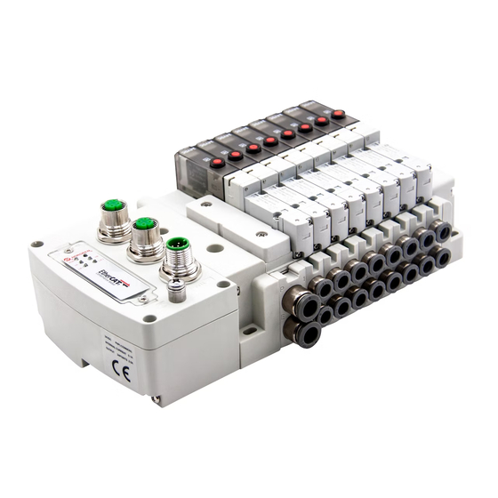
Installation & Maintenance Instruction VR10 / VR15 VALVE ISLAND Note: All images shown in this document are indicative only. If there is any inconsistency between the images and the actual product, the actual product shall govern. VR10 / VR15 OVERVIEW §... - Page 6 Installation & Maintenance Instruction VR10 / VR15 VALVE ISLAND Easy to identify operation with LEDs next to solenoids. Solenoid A (14 Solenoid) turns on red LED, and Solenoid B (12 Solenoid) turns on green LED. Industrial universal Electrical Interface D-Sub Connector 25-Pin IP40 version...
- Page 7 Installation & Maintenance Instruction VR10 / VR15 VALVE ISLAND Certifications RoHs REACH and CE Dual 3/2 valves available in 3 configurations. NC/NC NO/NO External pilot available for use in low pressure NC/NO or vacuum applications Fast response Maximum length of 24 stations/solenoids.
-
Page 8: Safety, Warnings
Before using this product with fluids other than those specified, for non-industrial applications, life-support systems, or other applications not within published specifications, consult IMI Norgren. Through misuse, age, or malfunction, components used in fluid power systems can fail in various modes. The system designer is warned to consider the failure modes of all component parts used in fluid power systems and to provide adequate safeguards to prevent personal injury or damage to equipment in the event of such failure. -
Page 9: Installation And Maintenance
Installation & Maintenance Instruction VR10 / VR15 VALVE ISLAND 4 INSTALLATION AND MAINTENANCE INSTALLATION AND OPERATION 4.1.1 Overview § DIN Rail is optional depending on your requirement. § 2-10 stations: one Sup/Exh (supply/exhaust) Module is required. § 11-24 stations: two Sup/Exh Modules are recommended. -
Page 10: Tools
Installation & Maintenance Instruction VR10 / VR15 VALVE ISLAND 4.1.2 Tools VR10: § Phillips screwdriver size #00 § Phillips screwdriver size #1 § Phillips screwdriver size #2 § Slotted screwdriver 3mm VR15: § Phillips screwdriver size #1 § Phillips screwdriver size #2 §... -
Page 11: Manual Override Operation
Installation & Maintenance Instruction VR10 / VR15 VALVE ISLAND 4.1.5 Manual Override Operation VR10: Solenoid B (12 Solenoid) Manual Push Only Green button Solenoid A (14 Solenoid) Manual Push Only Red button Valve Body VR15: Solenoid B (12 Solenoid) Manual Push Only... -
Page 12: Assembling And Disassembling
4.1.6.1 Torque List and Its Location • IP65 Valve Island 0.7-0.8 Nm | 6.2-7.1 lbf·in 0.15-0.2 Nm | 1.3-1.8 lbf·in (VR10 series) 0.4-0.5 Nm | 3.5-4.4 lbf·in (VR15 series) 0.4-0.5 Nm | 3.5-4.4 lbf·in 0.4-0.5 Nm | 3.5-4.4 lbf·in... - Page 13 Installation & Maintenance Instruction VR10 / VR15 VALVE ISLAND • IP40 Valve Island 0.15-0.2 Nm | 1.3-1.8 lbf·in (VR10 series) 0.7-0.8 Nm | 6.2-7.1 lbf·in 0.4-0.5 Nm | 3.5-4.4 lbf·in (VR15 series) 0.4-0.5 Nm | 3.5-4.4 lbf·in 0.7-0.8 Nm | 6.2-7.1 lbf·in 0.4-0.5 Nm | 3.5-4.4 lbf·in...
- Page 14 Installation & Maintenance Instruction VR10 / VR15 VALVE ISLAND 4.1.6.2 Assembling and Disassembling Control Module (IP65 Version) § Disassemble control module 1) Disassemble all three screws on control module. 2) Pull out control module § Assemble control module 1) Push in control module 2) Assemble all three screws on control module.
- Page 15 Installation & Maintenance Instruction VR10 / VR15 VALVE ISLAND 4.1.6.3 Changing Orientation of D-Sub Connector (IP40 Version) D-Sub connector housing § Disassemble D-Sub connector housing 1. Disassemble two screws on D-Sub connector housing 2. Pull out D-Sub connector housing slowly and make sure the wires are not damaged. (Wires are not shown) §...
- Page 16 Installation & Maintenance Instruction VR10 / VR15 VALVE ISLAND 4.1.6.4 Assembling and Disassembling D-Sub Connector (IP40 Version) D-Sub connector housing § Disassembling D-Sub connector 1. Disassemble two screws on D-Sub connector 2. Pull out D-Sub connector slowly. Make sure the connector is in its place.
- Page 17 Installation & Maintenance Instruction VR10 / VR15 VALVE ISLAND IMPORTANT: 1. The red wire must be connected to the upper position as shown below. 2. The PCB fitted must be located into the slot of the cover when assembling D-Sub connector.
- Page 18 Installation & Maintenance Instruction VR10 / VR15 VALVE ISLAND 4.1.6.5 Assembling and Disassembling Manifold § Disassembling Manifold Valve manifold can be disassembled after control module / D-Sub connector is removed. Disassemble tie rod screws on left endplate. Lift latch on right endplate.
- Page 19 Installation & Maintenance Instruction VR10 / VR15 VALVE ISLAND § Assembly Manifold (right endplates as example) 1. Put flat end side of tie rods into right endplate, then attach screws to tie rods. 2. Insert tie rods into valve stations and push to close the gap.
- Page 20 Installation & Maintenance Instruction VR10 / VR15 VALVE ISLAND Note: Expansion tie rod kits should be assembled to the round side and any gaps closed before inserting into valve stations. Construction & Design is subject to change (A1743-OPM-MX / Rev.004)
- Page 21 Installation & Maintenance Instruction VR10 / VR15 VALVE ISLAND 4.1.6.6 Assembling and Disassembling Sub-base or Sup/Exh Module (ISEM) After endplates and tie rods been removed, the sub-base and ISEM can be disassembled by following steps. § Disassembly Latch 1) Put a slotted screwdriver into 2) Lift latch slowly until mechanical the gap of sub-base &...
- Page 22 In case of adding valve stations or ISEM, tie rod expansion kits are available as below: Part number: VR**7516MM07##NA. * *: - Insert 10 for VR10; or 15 for VR15. ##: - Insert MS: ISEM expansion rod M1: 1 Station modular rod M2: 2 Stations modular rod Construction &...
- Page 23 Installation & Maintenance Instruction VR10 / VR15 VALVE ISLAND 4.1.6.7 Assembling and Disassembling Valve Slices § Disassembling Valve Slice 1. Remove 2 screws on valve body by using a Phillips screwdriver. 2. Lift the valve which will be replaced. Construction & Design is subject to change (A1743-OPM-MX / Rev.004)
- Page 24 Installation & Maintenance Instruction VR10 / VR15 VALVE ISLAND § Assemble Valve Slice 1. Drop the valve into its position and insert tab correctly. See view A. VIEW A 2. Tighten 2 screws with correct torque lock the valve onto sub-base.
- Page 25 Installation & Maintenance Instruction VR10 / VR15 VALVE ISLAND 4.1.6.8 Assembling and Disassembling Fittings ATTENTION: Make sure air pressure is released before unlocking the locking pins. Make sure the locking pin is properly installed before applying air pressure. § VR10 Fitting Disassembly 1.
- Page 26 Installation & Maintenance Instruction VR10 / VR15 VALVE ISLAND § VR15 Fitting Disassembly 1. Lift fitting lock clips with tool such as slotted screwdriver slowly to unlock position. 2. Pull the fittings out by using a piece of inserted tube or other means.
- Page 27 Installation & Maintenance Instruction VR10 / VR15 VALVE ISLAND § ISEM Fitting Disassembly 1. Lift fitting lock clips with tool such as slotted screwdriver slowly to unlock position. 2. Pull the fittings out by using a piece of inserted tube or other means.
- Page 28 Installation & Maintenance Instruction VR10 / VR15 VALVE ISLAND § External Pilot Base Fitting Disassembly 1. Loosen the screw and remove external pilot base. 2. Remove locking pin by pushing a flat bladed screwdriver into the hole on the underside of the external pilot block.
- Page 29 Installation & Maintenance Instruction VR10 / VR15 VALVE ISLAND § External Pilot Base Fitting Assembly 1. Push the fitting into the port until it hits the bottom position. Press locking pin to its bottom position to lock the fittings. 3. Assemble the external pilot base and tighten the screw.
- Page 30 Installation & Maintenance Instruction VR10 / VR15 VALVE ISLAND § VR10/VR15 Fitting Service Kit Description Part number Where used VR10 External Pilot Base Locking Pin A1743-870 VR15 External Pilot Base Locking Pin A1743-871 VR10 Sub-Base Locking Pin VR10 Supply Exhaust Module;...
- Page 31 Installation & Maintenance Instruction VR10 / VR15 VALVE ISLAND 4.1.6.9 Assembling and Disassembling DIN Rail § Locking torque and structure for DIN Rail clamp Right end plate DIN Rail Left end plate Fix DIN Rail 0.7-0.8 Nm 6.2-7.1 lbf·in Fix DIN Rail 0.7-0.8 Nm...
- Page 32 Installation & Maintenance Instruction VR10 / VR15 VALVE ISLAND § Assembling valve station onto DIN Rail. 1. Loose the screws of DIN Rail clamp. 2. Attach slot at fitting side of the manifold to DIN Rail, then push valve island to lock position as shown.
-
Page 33: Piping
Installation & Maintenance Instruction VR10 / VR15 VALVE ISLAND 4.1.7 Piping § Tube Insertion 1. Cut tubes as per best practice and avoid torn or irregular cut. 2. Insert tube into fittings until it reaches its end position. 3. Slowly and softly pull the tube to check if tube is hooked firmly. -
Page 34: Multi-Pressure Zone Option
In this case, the Sup/Exh Module for internal pilot zone shall not have silencer incorporated. Please find ordering information of Sup/Exh Module & blank plug in the VR10 / VR15 data sheet. Zone 3... -
Page 35: Maintenance
MAINTENANCE 4.2.1 Lubrication VR10 / VR15 valves will function reliably when they are supplied with clean dry air. If the air supply is lubricated from the beginning, then lubrication must be supplied for the life of the product. 4.2.2 Valve Identification Information When purchasing assembled valve islands from NORGREN, valve identification information is included. -
Page 36: Technical Data
Installation & Maintenance Instruction VR10 / VR15 VALVE ISLAND 6 TECHNICAL DATA SPECIFICATION 6.1.1 Operation § Dynamic soft seal spool valve, solenoid pilot operated. 6.1.2 Flow Rate § VR10: 5/2 valve: 220 L/min, Cv 0.22, Kv 0.20 5/3 valve: 270 L/min, Cv 0.27, Kv 0.24 2X3/2 valve: 220 L/min, Cv 0.22, Kv 0.20... -
Page 37: Medium
If air source is lubricated, then lubrication must be supplied for the life of the product because the lubricant will wash away all the initial lubrication and shorten valve life. For more information, please refer to VR10 / VR15 data sheet or consult NORGREN. MATERIALS... -
Page 38: Pneumatic
Installation & Maintenance Instruction VR10 / VR15 VALVE ISLAND PNEUMATIC 6.3.1 Response Time § Response time measurements are taken according to ISO 12238. § The typical response time of valve switching is 15ms on / 25ms off (when downstream pressure is at 90% upstream pressure). -
Page 39: Life Expectation
(internal pilot supply) 6.3.4 Life Expectation § All VR10 valve types can achieve 30 million cycles at 5 Hz, measurements are taken according to ISO 19973-1. § All valve types, except 3/2 NO, of VR15 can achieve 30 million cycles at 5 Hz, measurements are taken according to ISO 19973-1. -
Page 40: Electrical
Installation & Maintenance Instruction VR10 / VR15 VALVE ISLAND ELECTRICAL 6.4.1 General Features for Valve Island with Protocols Supply Voltage: 24 VDC +/- 10% for control module Voltage Tolerance: +10%/-5% for solenoid valve Power Consumption: 0.45W (Energy saving type) M12x1-Female, 4-pin, D-coded for industrial... -
Page 41: General Features For Valve Island With Multipole D-Sub Connector
Installation & Maintenance Instruction VR10 / VR15 VALVE ISLAND 6.4.2 General Features for Valve Island with Multipole D-Sub Connector Supply Voltage: 12 VDC & 24 VDC Voltage Tolerance: +/- 10% Power Consumption: 0.45W (Energy saving type) Electrical Connection: D-Sub Connector 25-Pin... -
Page 42: Wiring Rules For Multipole Series
Installation & Maintenance Instruction VR10 / VR15 VALVE ISLAND 6.4.3 Wiring Rules for Multipole Series § The Multipole has 25 pins, and the output follows rules below: If valve stations £ 12, 2 pins are always reserved for each valve station. *... - Page 43 Installation & Maintenance Instruction VR10 / VR15 VALVE ISLAND If 12 < valve stations £ 24, special connection is required since only 1 pin is allocated to valve station with single solenoid: § Step 1: Sequence all solenoids following the rules below by starting from 1st station which is the station closest to control module: 1.
- Page 44 Installation & Maintenance Instruction VR10 / VR15 VALVE ISLAND 16-station valve island example is shown as below: Station Pin No. of Solenoid A (14 Solenoid) Pin No. of Solenoid B (12 Solenoid) Note: *For valve station with single solenoid, only Pin No. of Solenoid A (14 Solenoid) is allocated & connected.
-
Page 45: Pin Allocating & Wire Colours Identifying For Multipole Series
Solenoid 12-b White/Green Common * This table is applicable to the D-Sub cables that NORGREN supplies, IP65 cable. Part numbers V11569-E01, V11569-E03 and V11569-E05. * The red border example indicates corresponding relation among pins, solenoids, pilot coil and stations based on configuration (12 stations, double solenoids) shown in table in section 6.4.3. - Page 46 Solenoid 12-b Green Common * This table is applicable to the D-Sub cables that NORGREN supplies, IP40 cable. Part numbers VR10569-E15, VR10569-E03 and VR10569-E05. * The red border example indicates corresponding relation among pins, solenoids, pilot coil and stations based on configuration (12 stations, double solenoids) shown in table.
-
Page 47: Wire Connection For Valve Island With Protocols
Installation & Maintenance Instruction VR10 / VR15 VALVE ISLAND 6.4.5 Wire Connection for Valve Island with Protocols § Connector identification for PROFINET / EtherNet/IP / EtherCAT protocol § Proper grounding will assure the safety and noise resistance for the valve island. Grounding should be close to the product. - Page 48 Installation & Maintenance Instruction VR10 / VR15 VALVE ISLAND § Pin Allocatinon of Port 1 / Port 2 M12 / 4 pins / Female Connector / D-coded Pin No. Function Transmission Data + (TD +) Receive Data + (RD +)
- Page 49 Installation & Maintenance Instruction VR10 / VR15 VALVE ISLAND § Control Module Connection for IO-Link Device IO-Link connector M12x1-Male 5-pin, A-coded GROUND Earth screw M4 Construction & Design is subject to change (A1743-OPM-MX / Rev.004)
- Page 50 Installation & Maintenance Instruction VR10 / VR15 VALVE ISLAND § Pin Allocation Of IO-Link Connector M12 / 5 pins / male connector / A-coded / Class B Pin No. Function L+ (VB+) 24V electronics power supply 2L+ (VA+) 24V valves power supply...
-
Page 51: Compliance And Approvals
Installation & Maintenance Instruction VR10 / VR15 VALVE ISLAND COMPLIANCE AND APPROVALS The VR10 / VR15 Protocol / Multipole series products are tested and compliant to: 6.5.1 CE marking Electromagnetic compatibility: EN 61000-6-4:2007 + A1:2011 Generic standards – Emission standard for industrial environments EN IEC 61000-6-2:2019 Generic standards –... -
Page 52: Customer Support
VR10 / VR15 VALVE ISLAND 7 CUSTOMER SUPPORT Norgren operates four global centres of technical excellence and a sales and service network in 50 countries, as well as manufacturing capability in the USA, Germany, China, UK, Switzerland, Czech Republic, Mexico and Brazil. - Page 53 50 countries, as well as manufacturing capability in Brazil, China, Czech Republic, Germany, India, Mexico UK and the USA. For information on all Norgren companies visit www.norgren.com Supported by distributors worldwide. Norgren, Buschjost, FAS, Herion,...
Need help?
Do you have a question about the VR10 and is the answer not in the manual?
Questions and answers