Table of Contents
Advertisement
Quick Links
Operation Manual
Proportional Valve VP60 Series
Before starting work read these instructions.
This manual contains proprietary information. No part of this
publication may be reproduced, transcribed or transmitted
in any form without the written consent of the publisher.
Every effort has been made to ensure that the information
contained in this manual is accurate. All rights reserved.
Advertisement
Table of Contents

Subscribe to Our Youtube Channel
Related Manuals for Norgren VP60 Series


Summary of Contents for Norgren VP60 Series
- Page 1 Operation Manual Proportional Valve VP60 Series Before starting work read these instructions. This manual contains proprietary information. No part of this publication may be reproduced, transcribed or transmitted in any form without the written consent of the publisher. Every effort has been made to ensure that the information...
-
Page 2: Table Of Contents
This document, as well as the data, specifications and other information presented in it are the sole property of Norgren. It may notbe reproduced or given to third parties without their consent. Our policy is one of continued research and development. We therefore reserve the right to amend, without notice, the specifications given in this document. -
Page 3: General
VP60 Analogue / IO-Link 1. General 1.1 Information about these Instructions These instructions will enable you to safely install, set up and operate the proportional valve VP60 in the analogue or IO-Link version. These instructions are an integral part of the product and must be accessible topersonnel. Personnel must carefully read through and understand these instructions before starting work of any kind on the valves. -
Page 4: Liability
This product is for use in industrial compressed air systems only. It is to be used where the pressure and temperature ratings listed in the data sheet are not exceeded. Contact Norgren directly before using the product in non-industrial applications, in life support or other systems not covered in the published instructions. -
Page 5: Functional Safety
VP60 Analogue / IO-Link 3. Functional Safety Note: The VP60 is not a design with design-related fail-safe properties. Therefore, no safety-related properties can be guaranteed at valve level. For machine controls (complex mechatronic systems) with the VP60, a risk analysis in accordance with e.g. EN-ISO12100 is urgently recommended. -
Page 6: Basic Function
VP60 Analogue / IO-Link 4. Basic function 4.1. General Description The VP60 is a 5/3-way proportional valve of nominal size 8. The flow-optimised, metal-seated 5/3-way spool is adjusted as quickly as possible to the position corresponding to the setpoint by means of a moving coil and position sensor via a µP control loop. In the production process, a setpoint / setpoint travel map is determined for each VP60 in such a way that a linear relationship between setpoint and flow results under constant pressure conditions. - Page 7 VP60 Analogue / IO-Link 4.3.1. Function Type (5/3-way) Filtered compressed air (see technical features) is available at port 1. The actuator (2.e. cylinder) is connected to ports 2 and 4. Ports 3 and 5 are used for venting. Silencers with low flow resistance should be connected here.
-
Page 8: Pneumatic Connection
VP60 Analogue / IO-Link 5. Pneumatic Connection 5.1 Block Diagram of the Valve Function (5/3 way) Port size 1: System pressure Port size 2: Operation Connection Port size 3: Venting working connection 2 Port size 4: Operation Connection Port size 5: Venting working connection 4 5.2 Operating Medium These units are designed for use with clean, dry, oil-free compressed air. -
Page 9: Electrical Connection
VP60 Analogue / IO-Link 6. Electrical Connection 6.1 Pin Assignment 6.1.1 Variant Analogue Colour (Typ.) Ref. Port size white Setpoint input current 4..20 mA (load resistance 500R) brown fault Error output (max.15mA to GND Vs) green Setpoint input voltage difference negative (0..10V /-5-5V) yellow Setpoint input voltage difference positive (0..10V /-5-5V) grey... - Page 10 VP60 Analogue / IO-Link Note: The actuator system (= position controller of the valve spool) is activated from a supply voltage of 21 V. Although the average current consumption (at 24 V over 10 seconds is limited to 0.6 A and is reversibly reduced to 0.2 A if exceeded, peaks of up to 1.5 A can occur.
-
Page 11: Assembly Instructions
The valve may only be mounted through the two mounting holes of the valve mechanism. 7.3 Accessories: Detailed ordering information on available accessories can be found in the product data sheet or on our homepage: https://www.norgren.com Our policy is one of continued research and development. We therefore reserve the right TCF Fellbach (2021).011 to amend, without notice, the specifications given in this document. -
Page 12: Troubleshooting And Diagnosis
VP60 Analogue / IO-Link 8. Diagnostics and Troubleshooting 8.1. LED Function 8.1.1. Analogue Version: LED STATUS red: Valve system fault -> check overvoltage at / if necessary. green: The position control of the valve piston is active. 8.1.2. IO-Link Version: Flashed green. - Page 13 VP60 Analogue / IO-Link 8.2. Status Byte You can access the status via VPTool or via the IO-Link parameter Index 70 Sub Index 0, as well as in the IO-Link process data. Values in the status byte are signaled via the "STATUS" or the "SF" LED, depending on the variant. Status byte Detailed device status Error description...
- Page 14 VP60 Analogue / IO-Link 8.4. Status Byte Error/fault Possible cause Troubleshooting measure -Output flow too low or not proportional - Connection cross section too small -Check and enlarge if necessary - Check voltage and ensure if necessary , check for -no control / maximum flow only - Supply voltage missing/too low current limitation...
-
Page 15: Transport And Storage
VP60 Analogue / IO-Link 9. Transport and Storage The individual packages are packed according to the expected transport conditions. 9.1. Transport Note: The valve and its components can be damaged by transport, corrosion or penetrating foreign bodies. - Transport the valve in the delivery packaging - Do not throw or drop packages - Do not remove the valve from its packaging until immediately before assembly. -
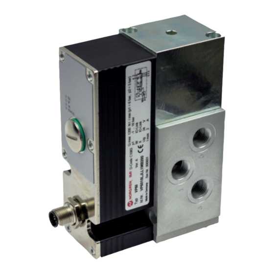
Page 16: Appendix
VP60 Analogue / IO-Link 11. Annex 11.1 Component View Connector Protective cover USB connection Housing Actuator magnet unit Valve mechanics 11.2. Dimensions Our policy is one of continued research and development. We therefore reserve the right TCF Fellbach (2021).016 to amend, without notice, the specifications given in this document. 03/21... - Page 17 VP60 Analogue / IO-Link 11.3 Markings Nameplate exemplary: The nameplate contains the following information: - Manufacturer - Connection schemes - Model Identification number with version - Pressure range Inlet pressure p1 - Setpoint W / Actual value X - Flow - Supply voltage Ub - Limit current I max - Date code, five digits, year/week/day...
- Page 18 VP60 Analogue / IO-Link 11.4.Characteristics Flow rate as a function of the set point and P1; P2, P4 = 0 bar (fei outflow): Flow direction 5000 4600 4000 3600 3000 2600 2000 1600 1000 1023 2047 IO-Link 0...............1024..............2047 IO-Link 10,4 13,6 15,2 16,8 18,4...
- Page 19 VP60 Analogue / IO-Link Flow rate as a function of the set point at constant pressure P1 = 6 bar; P2, P4 = 5 bar: Flow direction 0...............1024..............2047 IO-Link Input Our policy is one of continued research and development. We therefore reserve the right TCF Fellbach (2021).019 to amend, without notice, the specifications given in this document.
- Page 20 VP60 Analogue / IO-Link Frequency response and phase of the slider position Flow rate as a function of pressure ratio controller at 10, 50 and 100% setpoint: P2/P1 at set points 10, 20, to 100%: Valve in Function 5/3. 0% corresponds to the middle position. 11.5.
- Page 21 Access to the USB interface is gained after removing the cap on the connection lid. Device-specific Information The IODDs required for configuring the IO-Link unit and detailed information about the process data structure, diagnostic information and parameter addresses can be found at:https://www.norgren.com/de/de/technical-service/software 11.7. IO-Link Process Data Name...
- Page 22 50 countries, as well as manufacturing capability in Brazil, China, Czech Republic, Germany, India, Mexico UK and the USA. For information on all Norgren companies visit www.norgren.com Supported by distributors worldwide. Norgren, Buschjost, FAS, Herion,...
Need help?
Do you have a question about the VP60 Series and is the answer not in the manual?
Questions and answers