Zimmer LWR50F Series Installation And Operating Instructions Manual
Hide thumbs
Also See for LWR50F Series:
- Installation and operating instructions manual (28 pages) ,
- Installation and operating instructions manual (32 pages)

Related Manuals for Zimmer LWR50F Series


Summary of Contents for Zimmer LWR50F Series
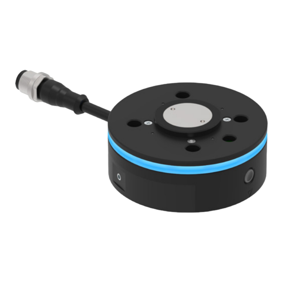
- Page 1 INSTALLATION AND OPERATING INSTRUCTIONS Fixed part LWR50F series DDOC01074 THE KNOW-HOW FACTORY www.zimmer-group.com...
-
Page 2: Table Of Contents
INSTALLATION AND OPERATING INSTRUCTIONS: Fixed part, LWR50F series Contents Supporting documents ................................. 3 Notices and graphics in the installation and operating instructions ........................3 Safety notices ..................................4 Proper use ..................................... 5 4 Personnel qualification ................................. 5 Product description ................................6 Forces and torques ........................................7 Type plate .............................................7... -
Page 3: Supporting Documents
The documents listed below are available for download on our website www.zimmer-group.com. • Installation and operating instructions • Catalogs, drawings, CAD data, performance data •... -
Page 4: Safety Notices
• Use of the product under extreme conditions, such as aggressive fluids or abrasive dusts • Additional drilled holes or threads Ö Zimmer GmbH shall accept no liability for any damage caused by improper use. The operator bears sole responsibility. Installation, commissioning, maintenance and repairs may only be performed by qualified specialists in accordance with these installation and operating instructions. -
Page 5: Proper Use
► Operate the product only when it is in a technical condition that corresponds to the guaranteed parameters and operating conditions. Ö Zimmer GmbH shall accept no liability for any damage caused by improper use. The operator bears sole responsibility. -
Page 6: Product Description
Fixed part, LWR50F series 5 Product description The new multifunctional end-of-arm platform of Zimmer Group is equipped with an extensive portfolio of functions and with universal communication interfaces. MATCH is compatible with any lightweight construction robot in the market. Installation of MATCH is incredibly easy. The system can be mounted to the robot flange and set up conveniently with just a few manual adjustments. -
Page 7: Forces And Torques
For information on the forces and torques for the following product, please refer to our website at www. zimmer-group.com: • LWR50F series Please contact Zimmer Customer Service if you have any questions. 5.2 Type plate A type plate is attached to the housing of the product. The part number and the serial number are shown on the type plate. -
Page 8: Function
Due to the differently sized centering pins and marks on the loose parts, the fixed part cannot be installed backwards. For information on the compatible loose parts, please refer to our website at www.zimmer-group.com. The product is equipped with a hot-plug function, which allows for the replacement of a loose part while electrically live. The loose part is designed in such a way that incorrect insertion into the storage station is not possible. -
Page 9: Led Display (Optional)
Fixed part, LWR50F series 6.1 LED display (optional) An LED ring is optionally available for the product. The colors of the LED ring reflect the status of the IO-Link device in the loose part. The LED ring enables a 360° status display. LED state Function of the Zimmer IO-Link products Function of the Schmalz IO-Link products None No supply voltage. No supply voltage. Flashing No connection to the IO-Link device. -
Page 10: Sensors
INSTALLATION AND OPERATING INSTRUCTIONS: Fixed part, LWR50F series 6.3 Sensors Example depiction of a combination consisting of a fixed part, loose part with gripper and storage station. Check up to two sensors in the storage position to see whether the loose part is present in the storage station. Then move the fixed part on the loose part from above. The centering pins of the loose part help in insertion. The robot, along with the fixed part and loose part, moves to the front position of the storage station. The two sensors in the inspection position (test channel) respond if the lockings are extended and make contact in the fixed part. When the fixed and loose part are joined, the internal spring-pin contacts for signal transmission are contacted. Then, the Connect LED changes color from red to green and a Connect signal (depending on the variant) is passed to the higher-level control system. -
Page 11: Functional Safety
INSTALLATION AND OPERATING INSTRUCTIONS: Fixed part, LWR50F series 6.3.1 Wiring diagram of the sensor system Sensor plug connection M8 3-pin: Circuit for sensor in storage position Circuit of two sensors in inspection position Power Supply Power Supply Safety Input Safety Input Safety Input 6.3.2 Setting the inspection position of the sensors... -
Page 12: Electrical Specifications
Fixed part, LWR50F series 6.5 Electrical specifications INFORMATION For electrical specifications, please refer to our website at www.zimmer-group.com. This data varies within the series, depending on the specific design. Please contact Zimmer Customer Service if you have any questions. 6.6 Protection class NOTICE The product achieves protection class IP40 in all mounted positions of installation. 6.7 Technical data INFORMATION For technical data, refer to our website at www.zimmer-group.com. -
Page 13: Installation
• Strength class of the mounting screws: ≥ 8.8 (DIN EN ISO 4762) • Observe the tightening torque of the mounting screws. Ö Zimmer GmbH recommends verifying the permitted load-carrying capacity of the required screw connections in accordance with VDI 2230. • The exact installation positions can be found on the technical data sheet on our website. -
Page 14: Installing The Mechanical System
INSTALLATION AND OPERATING INSTRUCTIONS: Fixed part, LWR50F series 7.2 Installing the mechanical system NOTICE Non-compliance may result in material damage. The following work steps must be observed during installation: ► Insert the product into the robot arm by the connection ... -
Page 15: Installing The Power Supply
► Avoid the danger zone. NOTICE The cables that are used by Zimmer GmbH feature a minimum bending radius of 10 x the outer diameter. This bending radius must not be undershot! ► Freely suspended cables must be secured to prevent excessive motion loads or pinching. - Page 16 INSTALLATION AND OPERATING INSTRUCTIONS: Fixed part, LWR50F series 7.3.2 Installing LWR50F-01-03-A The selected fixed part is equipped with an integrated Smart Communication Module (SCM) with RS485 interface. For installation and commissioning Color Function Explanation White Signal RS485+ Brown Signal RS485- Connect signal: 24 V if loose part is Green Output 2 coupled. Freedrive signal: 24 V if Freedrive button Yellow Output 1 is pressed.
- Page 17 INSTALLATION AND OPERATING INSTRUCTIONS: Fixed part, LWR50F series 7.3.3 Installing LWR50F-08-01-A Color Function Explanation White 0 V supply voltage Brown + 24 V DC + 24 V DC supply voltage Informational messages, see installation Green Input 2 and operating instructions of the loose part. Informational messages, see installation Yellow Input 1 and operating instructions of the loose part.
- Page 18 INSTALLATION AND OPERATING INSTRUCTIONS: Fixed part, LWR50F series 7.3.4 Installing LWR50F-10-01-A Color Function Explanation Informational messages, see installation White Output 1 and operating instructions of the loose part. Informational messages, see installation Brown Input 1 and operating instructions of the loose part.
- Page 19 INSTALLATION AND OPERATING INSTRUCTIONS: Fixed part, LWR50F series 7.3.5 Installation of LWR50F-01-02-A and LWR50F-07-01-A Color Function Explanation White Analog output 0 to 10 V DC output Connect signal 24 V if loose part is coupled. Brown Output 3 Informational messages, see installation and operating instructions of the loose part. Informational messages, see installation...
- Page 20 INSTALLATION AND OPERATING INSTRUCTIONS: Fixed part, LWR50F series 7.3.6 Installing LWR50F-09-01-A Color Function Explanation Informational messages, see installation White Analog output and operating instructions of the loose part. Connect signal 24 V if loose part is coupled. Brown Output 3 Informational messages, see installation and operating instructions of the loose part.
-
Page 21: Static Charge
7.6 Installing accessories NOTICE Before installing an accessory, make sure it is suitable for use with the selected variant. Please contact Zimmer Customer Service if you have any questions. Zimmer GmbH Am Glockenloch 2 77866 Rheinau, Germany +49 7844 9138 0 ... -
Page 22: Operation
INSTALLATION AND OPERATING INSTRUCTIONS: Fixed part, LWR50F series 8 Operation 8.1 Freedrive operation (optional) For manual soft-switching of the robot, the product is equipped with a "Freedrive button" The following work steps must be observed for manually teaching in the robot position: ►... -
Page 23: Maintenance
Even though the product is maintenance-free as mentioned above, perform a regular visual inspection to check for any corrosion, damage or contamination. We recommend using Zimmer Customer Service for maintenance. Dismantling and reassembling the product without authorization may result in complications as special installation equipment is required in some cases. -
Page 24: Accessories/Scope Of Delivery
Fixed part, LWR50F series 10 Accessories/scope of delivery INFORMATION If any accessories not sold or authorized by Zimmer Group are used, the function of the product cannot be guaranteed. Zimmer Group accessories are specifically tailored to the individual products. Optional accessories and those included in the scope of delivery can be found at www.zimmer-group.com. -
Page 25: Rohs Declaration
INSTALLATION AND OPERATING INSTRUCTIONS: Fixed part, LWR50F series 13 RoHS declaration In terms of the EU Directive 2011/65/EU Name and address of the manufacturer: Zimmer GmbH Im Salmenkopf 5, 77866 Rheinau, Germany +49 7844 9138 0 +49 7844 9138 80 www.zimmer-group.com... -
Page 26: Declaration Of Incorporation
INSTALLATION AND OPERATING INSTRUCTIONS: Fixed part, LWR50F series 15 Declaration of Incorporation In terms of the EU Machinery Directive 2006/42/EC (Annex II 1 B) Name and address of the manufacturer: Zimmer GmbH Im Salmenkopf 5, 77866 Rheinau, Germany +49 7844 9138 0 ... -
Page 27: Declaration Of Conformity
INSTALLATION AND OPERATING INSTRUCTIONS: Fixed part, LWR50F series 16 Declaration of Conformity In terms of the EC Directive 2014/30/EC on electromagnetic compatibility Name and address of the manufacturer: Zimmer GmbH Im Salmenkopf 5, 77866 Rheinau, Germany +49 7844 9138 0 ... - Page 28 INSTALLATION AND OPERATING INSTRUCTIONS: Fixed part, LWR50F series Zimmer GmbH Am Glockenloch 2 77866 Rheinau, Germany +49 7844 9138 0 +49 7844 9138 80 www.zimmer-group.com • • • • •...
Need help?
Do you have a question about the LWR50F Series and is the answer not in the manual?
Questions and answers