Advertisement
Quick Links
Installation of the push-button panel
1
2
3
4
5
6
7
8
9
A
0
B
Mounting modules.
1
Fix lower part of the frame to the
rain shelter and make the elec-
trical connections.
2
Fixing of the module frames on the
upper side by the 2 small screws
included in the rain shelter.
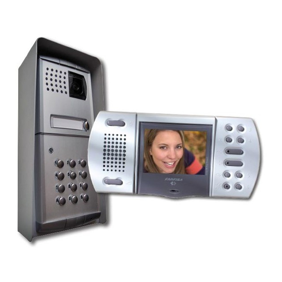
ONE-WAY VIDEOKIT
3
ADJUSTMENTS
Transmitter adjustable
volume
Receiver
volume
Anti-feedback adjust-
ment (Larsen effect)
Pan-tilt of the camera
(±15°)
ACI srl Farfisa Intercoms
Via E. Vanoni, 3 • 60027 Osimo (AN) • Italy
Tel: +39 071 7202038 (r.a.) • Fax: +39 071 7202037
e-mail: info@acifarfisa.it • www.acifarfisa.it
ACI Farfisa Intercoms reserves the right to modify the products illustrated at any time.
4
Fixing of frame to rain shel-
ter. Align the frame before
tightening the screws.
FC52PL
adjustable
PL41PCED
Dispose of the device in accordance
with environmental regulations.
EH9161FPLCW
MI 2498
1
2
3
4
5
6
7
8
9
A
0
B
NC2 NA2
C2
NC1 NA1
C1
P1 P2
S L+ Y
X
F H
- 1 -
Advertisement

Related Manuals for FARFISA INTERCOMS EH9161FPLCW


Summary of Contents for FARFISA INTERCOMS EH9161FPLCW
- Page 1 Via E. Vanoni, 3 • 60027 Osimo (AN) • Italy with environmental regulations. Tel: +39 071 7202038 (r.a.) • Fax: +39 071 7202037 e-mail: info@acifarfisa.it • www.acifarfisa.it - 1 - ACI Farfisa Intercoms reserves the right to modify the products illustrated at any time.
- Page 2 INSTALLATION DIAGRAMS 127V 230V 127V 230V VERY IMPORTANT To comply with the European Standards on Electromagnetic Compat- ibility and to increase the reliability of the product, it is necessary to connect a suppression device when switching inductive loads i.e. electric releases and electric locks. The enclosed suppression devices (transil) must be connected as close as possible to the loads (ideally...
- Page 3 CABLES Terminals Distance Note. For distances longer than 100m (330ft) max 200m 165 Ft 100m 330 Ft 200m 660 Ft (660ft) use twisted pair wire for conductores X and Y. (mm²) (AWG) (mm²) (AWG) (mm²) (AWG) X . Y 0.35 0.35 0.35 F .
- Page 4 - enter a number from 00 to 99 to programme BISTABLE OPERATION Table of codes activation time of relay 1 (enter 00 to deac- This function is possible only if the keypad Master pro- tivate the relay) has been programmed properly. See “Chang- gramming code - press key A ing the relay activation time and mode”.
Need help?
Do you have a question about the EH9161FPLCW and is the answer not in the manual?
Questions and answers