Advertisement
Quick Links
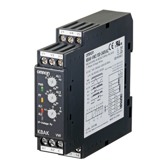
Single-phase Overvoltage/Undervoltage Relays
K8AK-VW
Ideal for voltage monitoring for
industrial facilities and equipment.
• Monitor for overvoltages and undervoltages simultaneously.
Separate settings and outputs supported for overvoltages and
undervoltages.
• Manual resetting and automatically resetting supported by one
Relay.
• Pre-alarm Monitoring Mode.
• Two SPDT output relays, 5 A at 250 VAC (resistive load).
• Process control signal (0 to 10 V) and current splitter input
supported.
• Output status can be monitored using LED indicator.
• Input frequency of 40 to 500 Hz supported.
• Inputs are isolated from the power supply.
Refer to Safety Precautions for the K8AK Series on page 86.
Refer to page 38 for commonly asked questions.
Ordering Information
List of Models
Setting range
Supply voltage
1 to 10 V AC/DC
24 VAC/DC
3 to 30 V AC/DC
100 to 240 VAC
15 to 150 V AC/DC
20 to 200 V AC/DC
24 VAC/DC
30 to 300 V AC/DC
100 to 240 VAC
60 to 600 V AC/DC
Ratings and Specifications
Input Range
Model
Range *
0 to 10 V AC/DC
K8AK-VW2
0 to 30 V AC/DC
0 to 150 V AC/DC
0 to 200 V AC/DC
K8AK-VW3
0 to 300 V AC/DC
0 to 600 V AC/DC
* The range is selected using connected terminals.
Model
K8AK-VW2 24 VAC/DC
K8AK-VW2 100 to 240 VAC
K8AK-VW3 24 VAC/DC
K8AK-VW3 100 to 240 VAC
Connection terminal
Setting range
V1-COM
1 to 10 V AC/DC
V2-COM
3 to 30 V AC/DC
15 to 150 V AC/DC
V3-COM
V1-COM
20 to 200 V AC/DC
V2-COM
30 to 300 V AC/DC
60 to 600 V AC/DC
V3-COM
For the most recent information on models that have been certified for
safety standards, refer to your OMRON website.
Input impedance
Approx. 120 kΩ
Approx. 320 kΩ
Approx. 1.6 MΩ
Approx. 1.2 MΩ
Approx. 1.7 MΩ
Approx. 3.1 MΩ
Overload capacity
Continuous input at 115% of
maximum input.
10 s at 125%
(up to 600 VAC)
1
Advertisement

Related Manuals for Omron K8AK-VW2


Summary of Contents for Omron K8AK-VW2
- Page 1 For the most recent information on models that have been certified for • Inputs are isolated from the power supply. safety standards, refer to your OMRON website. Refer to Safety Precautions for the K8AK Series on page 86. Refer to page 38 for commonly asked questions.
- Page 2 Power consumption 100 to 240 VAC: 4.6 VA max. 10% to 100% of the maximum value of the setting range K8AK-VW2: 1 to 10 V AC/DC 3 to 30 V AC/DC Operating value setting range (AL1 and AL2) 15 to 150 V AC/DC...
-
Page 3: Specifications
K8AK-VW Specifications Allowable operating voltage range 85% to 110% of rated power supply voltage Allowable operating frequency range 50/60 Hz ±5 Hz Input frequency range 40 to 500 Hz Overload capacity Continuous input at 115% of maximum input, 10 s at 125% (up to 600 VAC). ±0.5% full scale (at 25°C and an ambient humidity of 65% at the rated power supply voltage, DC and 50/60 Operating value Hz sine wave input) -
Page 4: Wiring Diagram
K8AK-VW Connections Wiring Diagram ●Undervoltage and Undervoltage Operation ●Overvoltage and Undervoltage Operation Diagram (Undervoltage Pre-alarm Mode) Diagram DIP switch settings: SW3 OFF and SW4 ON. DIP switch settings: SW3 and SW4 both ON or both OFF. Power supply voltage Input Power supply voltage Hysteresis: Fixed at 5% Undervoltage set value (AL1) - Page 5 K8AK-VW Nomenclature Front ●Indicators Item Meaning Terminal block Power indicator (See notes 1 and 2.) Lit when power is being supplied. (PWR: Green) Lit when relay operates (Not light when Relay status indicator both AL1 and AL2 are in error status) (Nor- (RY: Yellow) mally lit) Lit when there is an overvoltage or under-...
- Page 6 Operation and Setting Methods ●Setting Ranges and Wiring Connections Model Setting range Wiring connection 1 to 10 V AC/DC V1-COM K8AK-VW2 3 to 30 V AC/DC V2-COM 15 to 150 V AC/DC V3-COM 20 to 200 V AC/DC V1-COM K8AK-VW3...
- Page 7 K8AK-VW Dimensions (Unit: mm) Single-phase Voltage Relays K8AK-VW2 22.5 K8AK-VW3 Optional Parts for DIN Track Mounting ●DIN Tracks PFP-100N ±0.15 PFP-50N ±0.3 ±0.15 15 (5)* 1,000 (500)* *Dimensions in parentheses are for the PFP-50N.
- Page 8 K8AK-VW Questions and Answers How to Measure the Operating Time Checking Operation Overvoltage Overvoltages Change the input suddenly from 0% to 120% of the set value Gradually increase the input from 80% of the set value. and measure the time until the Unit operates. The input will equal the operating value when the input Undervoltage exceeds the set value and the alarm indicator starts flashing.
-
Page 9: Safety Precautions
Safety Precautions Be sure to read the precautions for all models in the website at the following URL: http://www.ia.omron.com/. Warning Indications If the K8AK-TH fails, the monitoring alarms and alarm outputs Indicates a potentially hazardous situation may fail to operate. This may result in physical damage to the... - Page 10 19.When cleaning the product, do not use thinners or solvents. Use • To remove the product, pull down on the bottom hook with a flat- commercial alcohol. blade screwdriver and lift up on the product. 20.Make sure the power and output indicators operate correctly. Depending on the application environment, the indicators and other plastic parts may wear prematurely and become difficult to see.
-
Page 11: Terms And Conditions Of Sale
Buyer indemnifies Omron against all related costs or expenses. rights of another party. 10. Force Majeure. Omron shall not be liable for any delay or failure in delivery 16. Property; Confidentiality. Any intellectual property in the Products is the exclu-... - Page 12 OMRON ELETRÔNICA DO BRASIL LTDA • HEAD OFFICE São Paulo, SP, Brasil • 55.11.2101.6300 • www.omron.com.br OMRON EUROpE B.V. • Wegalaan 67-69, NL-2132 JD, Hoofddorp, The Netherlands. • Tel: +31 (0) 23 568 13 00 Fax: +31 (0) 23 568 13 88 • www.industrial.omron.eu Cat.
Need help?
Do you have a question about the K8AK-VW2 and is the answer not in the manual?
Questions and answers