Table of Contents
Advertisement
NEW Product
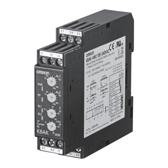
Single-phase Overcurrent/Undercurrent Relay
K8AK-AW
Ideal for Current Monitoring for
Industrial Facilities and Equipment.
• Monitor for overcurrents and undercurrents simultaneously.
Separate settings and outputs supported for overcurrents and
undercurrents.
• Use commercially available CTs (CT current on secondary
side: 0 to 1 A or 0 to 5 A).
• Manual resetting and automatically resetting supported by one
Relay.
• Startup lock and operating time can be set separately.
• Two sets of SPDT output contacts, 5 A at 250 VAC (resistive
load).
• Output status can be monitored using LED indicator.
• Inputs are isolated from the power supply.
Refer to Safety Precautions on page 12.
Refer to page 11 for commonly asked questions.
Ordering Information
List of Models
Setting range
Power supply voltage
2 to 20 mA AC/DC
24 VAC/DC
10 to 100 mA AC/DC
100 to 240 VAC
50 to 500 mA AC/DC
24 VAC/DC
0.1 to 1 A AC/DC
0.5 to 5 A AC/DC
100 to 240 VAC
24 VAC/DC
10 to 100 A AC*
20 to 200 A AC*
100 to 240 VAC
* The K8AK-AW3 is designed to be used in combination with an OMRON K8AC-CT200L Current Transformer (CT). (Direct input is not possible.)
Accessory (Order Separately)
●OMRON CT
Appearance
Input range
10 to 100 A AC,
20 to 200 A AC
Model
K8AK-AW1 24 VAC/DC
K8AK-AW1 100-240 VAC
K8AK-AW2 24 VAC/DC
K8AK-AW2 100-240 VAC
K8AK-AW3 24 VAC/DC
K8AK-AW3 100-240 VAC
Applicable
Model
Relay
K8AK-AW3
K8AC-CT200L
For the most recent information on models that have been certified for
safety standards, refer to your OMRON website.
●Commercially Available CTs*
Appearance
CT current on secondary side
0 to 1 A AC,
0 to 5 A AC
* If you use a commercially available CT, do not exceed the overload
capacity of the K8AK-AW2.
Applicable
Relay
K8AK-AW2
1
Advertisement
Table of Contents

Related Manuals for Omron K8AK-LS1 24VAC/DC


Summarization of Contents
Ordering Information
List of Models
Details the available models of the K8AK-AW relay, including setting ranges and power supply voltages.
Accessory (Order Separately)
OMRON CT Accessory
Details the OMRON CT accessory, including input range, applicable relay, and model.
Commercially Available CTs
Lists commercially available CTs, their secondary side current, and applicable relays.
Ratings and Specifications
Input Range Specifications
Details the input range, connection terminals, setting range, input impedance, input type, and overload capacity for each model.
Power Supply and Operating Details
Covers power supply, consumption, operating/reset values, methods, and timing settings.
Output Relay and Environmental Ratings
Details output relay ratings, ambient/storage conditions, altitude, and terminal specifications.
Physical and Mounting Specifications
Includes case color, material, weight, mounting type, and dimensions.
Operating Characteristics
Details voltage/frequency ranges, overload capacity, and repeat accuracy for the relay.
Standards and Protection
Covers applicable standards, insulation, dielectric strength, noise immunity, and protection ratings.
Connections
Terminal Diagram
Provides a visual representation of the terminal connections for the K8AK-AW relay and its components.
Wiring Examples
Demonstrates wiring configurations for directly inputting current and using a CT.
Example Relay Sequence
Timer Setting Conditions
Specifies timer settings (TA, operating mode, setting time) for relay sequences.
Timing Charts
Overcurrent/Undercurrent Monitoring Mode Diagram
Timing chart illustrating operation for overcurrent and undercurrent monitoring mode.
Overcurrent/Overcurrent Monitoring Mode Diagram
Timing chart for overcurrent monitoring mode, used for pre-alarm applications.
Nomenclature
Front Panel Nomenclature
Identifies and explains the components and indicators on the front panel of the K8AK-AW.
Front Panel Indicators
Details the meaning of the Power, Relay Status, and Alarm indicators on the front panel.
Front Panel Setting Knobs
Explains the usage of current, operating time, and startup lock time setting knobs.
Operation Methods
Setting Ranges and Wiring Connections
Details setting ranges and wiring connections for each model and input type.
DIP Switch Settings
Explains how to set resetting method, relay drive, and operating mode using DIP switches.
DIP Switch Functions
Details the functions of DIP switch pins for resetting, AL1, AL2, and operating mode.
Setting Current
Guides on setting the current using the current knob, covering range and adjustment.
Setting Adjustments
Operating Time Setting
Guides on setting the operating time using the dedicated knob, covering the adjustable range.
Startup Lock Time Setting
Guides on setting the startup lock time using the dedicated knob, preventing unwanted operations.
Dimensions
Relay Dimensions
Provides dimensional drawings for K8AK-AW1, K8AK-AW2, and K8AK-AW3 models.
OMRON CT Dimensions
Provides dimensional drawings and mounting hole details for the K8AC-CT200L.
DIN Track Mounting Accessories
Details optional parts for DIN track mounting, including PFP-100N and PFP-50N.
Questions and Answers
Checking Operation
Provides guidance on how to check the overcurrent and undercurrent operating modes.
Motor Monitoring Precautions
Addresses using the K8AK-AW with motor loads and application precautions.
How to Measure the Operating Time
Explains the procedure for measuring operating time for overcurrent and undercurrent.
Monitoring Switch-mode Power Supplies
Warns against monitoring switch-mode power supplies due to pulse current issues.
Safety Precautions
Warning Indications
Explains CAUTION and supplementary warning indications for safe use.
Product Safety Symbols
Defines the meaning of various product safety symbols used in the manual.
Precautions for Use
Precautions for Safe Use
Lists locations and conditions to avoid for safe storage and operation of the product.
Precautions for Correct Use
Provides guidance on operating methods to prevent failure and malfunction.
Correct Mounting Direction, Mounting, and Removing
Details the correct method for mounting and removing the product from a DIN track.
Adjusting the Setting Knobs
Advises on using a screwdriver to adjust setting knobs and respecting their stoppers.
Terms and Conditions Agreement
Warranties
Outlines Omron's exclusive warranty and limitations for the products.
Limitation on Liability
Specifies Omron's liability limitations for damages related to product use.
Suitability of Use
States buyer's responsibility for determining product suitability in specific applications.
Need help?
Do you have a question about the K8AK-LS1 24VAC/DC and is the answer not in the manual?
Questions and answers