Table of Contents
Advertisement
Quick Links
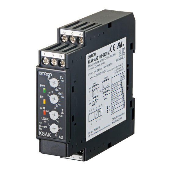
Single-phase Current Relay
K8AK-AS
Ideal for current monitoring for
industrial facilities and equipment.
• Monitor for overcurrents or undercurrents.
• Use commercially available CTs (CT current on secondary
side: 0 to 1 A or 0 to 5 A).
• Manual resetting and automatically resetting supported by one
Relay.
• Startup lock and operating time can be set separately.
• One SPDT output relay, 5 A at 250 VAC (resistive load).
• Output relay can be switched between normally open and
normally closed.
• Output status can be monitored using LED indicator.
• Inputs are isolated from the power supply.
Refer to Safety Precautions for the K8AK Series on page 86.
Refer to page 13 for commonly asked questions.
Ordering Information
List of Models
Setting range
2 to 20 mA AC/DC,
24 VAC/DC
10 to 100 mA AC/DC,
100 to 240 VAC
50 to 500 mA AC/DC
0.1 to 1 A AC/DC,
24 VAC/DC
0.5 to 5 A AC/DC,
100 to 240 VAC
0.8 to 8 A AC/DC
24 VAC/DC
10 to 100 A AC*,
20 to 200 A AC*
100 to 240 VAC
*1 The K8AK-AS3 is designed to be used in combina tion with an OMRON K8AC-CT200L Current Transformer (CT). (Direct input is not possible.)
Accessory (Order Separately)
●OMRON CT
Appearance
Input range
10 to 100 A AC,
20 to 200 A AC
1
Supply voltage
K8AK-AS1 24 VAC/DC
K8AK-AS1 100-240 VAC
K8AK-AS2 24 VAC/DC
K8AK-AS2 100-240 VAC
K8AK-AS3 24 VAC/DC
K8AK-AS3 100-240 VAC
Applicable
Model
Relay
K8AK-AS3
K8AC-CT200L
For the most recent information on models that have been certified for
safety standards, refer to your OMRON website.
Model
●Commercially Available CTs*
CT current on secondary
Appearance
0 to 1 A AC,
0 to 5 A AC
* If you use a commercially available CT, do not exceed the overload
capacity of the K8AK-AS2.
Applicable Relay
side
K8AK-AS2
Advertisement
Table of Contents

Related Manuals for Omron K8AK-AS1


Summary of Contents for Omron K8AK-AS1
- Page 1 20 to 200 A AC* 100 to 240 VAC K8AK-AS3 100-240 VAC *1 The K8AK-AS3 is designed to be used in combina tion with an OMRON K8AC-CT200L Current Transformer (CT). (Direct input is not possible.) Accessory (Order Separately) ●OMRON CT ●Commercially Available CTs*...
-
Page 2: Ratings And Specifications
1 s at 600% * CT capacity on primary side. *1 The range is selected using connected terminals. *2 The K8AK-AS3 is designed to be used in combination with an OMRON K8AC-CT200L Current Transformer (CT). (Direct input is not possible.) Ratings 24 VAC/DC... -
Page 3: Specifications
Continuous input at 120% of maximum input, 1 s at 150% Overload capacity K8AK-AS3: Continuous input at 120%, 30 s at 200%, and 1 s at 600% with an OMRON CT (K8AC-CT200L) Note: Overload capacity of primary side of CT. Operating value ±0.5% full scale (at 25°C and 65% humidity, rated power supply voltage, DC or 50/60 Hz sine wave input) -
Page 4: Terminal Diagram
Load ●Undercurrent Operation Diagram Note: 1. The K8AK-AS3 is designed to be used in combination with the OMRON K8AC-CT200L Current Transformer (CT). (Output Relay Drive Method: Normally Closed) 2. There is no polarity when a DC current input is used. - Page 5 K8AK-AS Nomenclature Front ●Indicators Item Meaning Terminal block Power indicator (See notes 1 and 2.) Lit when power is being supplied. (PWR: Green) Relay status indicator Lit when relay is operating. (RY: Yellow) Lit when there is an overcurrent or un- dercurrent.
-
Page 6: Dip Switch Settings
Malfunctions may occur if the input is connected to unused terminals and the Unit will not operate correctly. Terminal I1 is not used by the K8AK-AS3. K8AK-AS3 If using the OMRON K8AC-CT200L CT, connect to terminals k and l on the K8AC-CT200L. (Terminals kt and lt are not used.) Power supply voltage 2. - Page 7 81.5 33.5 30 dia. 14.5 14.5 Note: The OMRON Current Transformer (CT) is designed to be used with the K8AK-AS3. Use terminals k and l for connections. (Terminals kt and lt are not used.) Optional Parts for DIN Track Mounting ●DIN Tracks...
- Page 8 Output approximately 30 A. The startup current will exceed the Input terminals 0 to 10 A overload capacity (rating: 150% for 1 s) of the K8AK-AS1 and 30 Ω 100 VAC 400 W (two in parallel) K8AK-AS2 and result in failure of the Relay.
-
Page 9: Safety Precautions
Safety Precautions Be sure to read the precautions for all models in the website at the following URL: http://www.ia.omron.com/. Warning Indications If the K8AK-TH fails, the monitoring alarms and alarm outputs Indicates a potentially hazardous situation may fail to operate. This may result in physical damage to the... - Page 10 19.When cleaning the product, do not use thinners or solvents. Use • To remove the product, pull down on the bottom hook with a flat- commercial alcohol. blade screwdriver and lift up on the product. 20.Make sure the power and output indicators operate correctly. Depending on the application environment, the indicators and other plastic parts may wear prematurely and become difficult to see.
-
Page 11: Terms And Conditions Agreement
Buyer indemnifies Omron against all related costs or expenses. rights of another party. 10. Force Majeure. Omron shall not be liable for any delay or failure in delivery 16. Property; Confidentiality. Any intellectual property in the Products is the exclu-... - Page 12 OMRON ELETRÔNICA DO BRASIL LTDA • HEAD OFFICE São Paulo, SP, Brasil • 55.11.2101.6300 • www.omron.com.br OMRON EUROpE B.V. • Wegalaan 67-69, NL-2132 JD, Hoofddorp, The Netherlands. • Tel: +31 (0) 23 568 13 00 Fax: +31 (0) 23 568 13 88 • www.industrial.omron.eu Cat.
Need help?
Do you have a question about the K8AK-AS1 and is the answer not in the manual?
Questions and answers