
Related Manuals for Riello RS 1000/M BLU


Summary of Contents for Riello RS 1000/M BLU
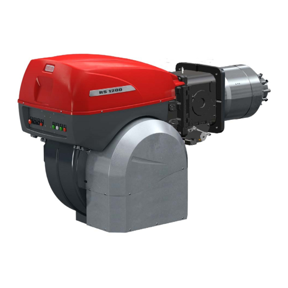
- Page 1 Installation, use and maintenance instructions Forced draught gas burners Progressive two-stage or modulating operation CODE MODEL TYPE 20145840 RS 1000/M BLU 1133 T 20145867 RS 1200/M BLU 1134 T 20145860 (2) - 10/2020...
- Page 2 Translation of the original instructions...
-
Page 3: Table Of Contents
Contents Declarations....................................3 Information and general warnings............................4 Information about the instruction manual ........................4 2.1.1 Introduction.................................. 4 2.1.2 General dangers................................4 2.1.3 Other symbols ................................4 2.1.4 Delivery of the system and the instruction manual...................... 5 Guarantee and responsibility............................5 Safety and prevention................................ - Page 4 Contents Burner ignition ................................25 Servomotor adjustment ..............................25 Burner adjustment and output modulation .........................25 6.6.1 Maximum output ................................25 6.6.2 Minimum output .................................25 6.6.3 Intermediate outputs ..............................26 Combustion air adjustment ............................26 Air / fuel adjustment ..............................26 6.8.1 Burner calibration procedure............................27 Pressure switch adjustment ............................27 6.9.1 Air pressure switch - check CO..........................27 6.9.2...
-
Page 5: Declarations
The quality is guaranteed by a quality and management system certified in accordance with ISO 9001:2015. Manufacturer's Declaration RIELLO S.p.A. declares that the following products comply with the NOx emission limits specified by German standard “1. BImSchV revision 26.01.2010”. Product... -
Page 6: Information And General Warnings
Information and general warnings Information and general warnings Information about the instruction manual 2.1.1 Introduction WARNING: MOVING PARTS The instruction manual supplied with the burner: This symbol indicates that you must keep limbs is an integral and essential part of the product and must not away from moving mechanical parts;... -
Page 7: Delivery Of The System And The Instruction Manual
Information and general warnings 2.1.4 Delivery of the system and the instruction The system supplier must carefully inform the user about: – the use of the system; manual – any further tests that may be required before activating the When the system is delivered, it is important that: system;... -
Page 8: Safety And Prevention
Safety and prevention Safety and prevention Introduction The burners have been designed and built in compliance with the type and pressure of the fuel, the voltage and frequency of the current regulations and directives, applying the known technical electrical power supply, the minimum and maximum deliveries for rules of safety and envisaging all the potential danger situations. -
Page 9: Technical Description Of The Burner
Voltage of auxiliaries : 230/50/60 230V / 50-60Hz 110/50/60 110V / 50-60Hz 1000 3/400/50 230/50 BASIC DESIGNATION EXTENDED DESIGNATION Models available Designation Voltage Start-up Code RS 1000/M BLU 3/400/50 Star/Triangle 20145840 RS 1200/M BLU 3/400/50 Star/Triangle 20145867 Tab. A 20145860... -
Page 10: Technical Data
Technical description of the burner Technical data Model RS 1000/M BLU RS 1200/M BLU Type 1133 T 1134 T Output min - max 1100/4000 - 10100 1500/5500 - 11100 Output Fuels Natural gas: G20 (methane gas) - G21 - G22 - G23 - G25 Gas pressure at max. -
Page 11: Maximum Dimensions
Bear in mind that inspection of the combustion head requires the burner to be opened and the rear part turned on the hinge. The l position is reference for the refractory thickness of the boiler door. 20058937 Fig. 1 RS 1000/M BLU 1637 DN80 1206 1338 1493... -
Page 12: Firing Rates
1013 mbar (approx. 0 m limit of the diagram: a.s.l.), and with the combustion head adjusted as WARNING RS 1000/M BLU = 4000 kW shown on page 18. RS 1200/M BLU = 5500 kW D11991 RS 1000/M BLU... -
Page 13: Burner Description
Technical description of the burner Burner description 20156496 Fig. 4 Lifting rings 16 Air damper movement leverage 17 Air pressure switch (differential operating type) Fan motor 18 Combustion head air pressure test point Servomotor 19 Maximum gas pressure switch with pressure test point Combustion head gas pressure test point 20 UV cell Combustion head... -
Page 14: Electrical Panel Description
Technical description of the burner 4.10 Electrical panel description 20156495 Fig. 5 Main terminal supply board 16 Plug/socket servomotor Clean contacts output relay 17 Light signalling of main fuel valve open Ignition transformer 18 Heat request light signalling Stop push-button 19 Light signalling of mains live state OFF-automatic-manual selector 20 Flame sensor plug/sensor socket... -
Page 15: 4.12 Rfgo-A22 Control Box
The control box is a safety device! Avoid opening WARNING or modifying it, or forcing its operation. Riello S.p.A. cannot assume any responsibility for dam- age resulting from unauthorised interventions! All interventions (assembly and installation operations, assistance, etc.) must be carried out by qualified personnel. -
Page 16: Servomotor (Sqm10.1
Technical description of the burner 4.13 Servomotor (SQM10.1..) Warnings To avoid accidents, material or environmental damage, observe the following instructions! Avoid opening, modifying or forcing the actua- WARNING tors. All interventions (assembly and installation operations, assistance, etc.) must be carried out by qualified personnel. ... -
Page 17: Installation
Installation Installation Notes on safety for the installation After carefully cleaning all around the area where the burner will The installation of the burner must be carried out be installed, and arranging the correct lighting of the environ- by qualified personnel, as indicated in this manual ment, proceed with the installation operations. -
Page 18: Operating Position
For boilers with front flue passes 1)(Fig. 12) or flame inversion chamber, a protection in refractory material 5) must be inserted RS 1000/M BLU M 20 between the boiler fettling 2) and the blast tube 4). -
Page 19: Securing The Burner To The Boiler
Installation Securing the burner to the boiler Prepare a suitable lifting system using rings The seal between burner and boiler must be 3)(Fig. 12). airtight. WARNING Insert the thermal protection supplied with the blast tube 4). Insert the entire burner on the boiler hole, previously fitted, as in Fig. -
Page 20: Electrodes Adjustment
Installation Electrodes adjustment Position the electrodes according to the dimen- Electrodes sions shown in Fig. 14. WARNING Diffuser D11587 Fig. 14 5.10 Combustion head adjustment The air damper servomotor 4)(Fig. 4), beyond varying the air out- The selection of the hole to be used is determined based on the put according to the output demand, through a leverage varies maximum output requested, as illustrated in Tab. -
Page 21: Gas Feeding
Installation 5.11 Gas feeding Explosion danger due to fuel leaks in the pres- MBC “threaded” ence of a flammable source. Precautions: avoid knocking, attrition, sparks and heat. Make sure that the fuel interception tap is closed before performing any operation on the burner. The fuel supply line must be installed by qualified personnel, in compliance with current standards and laws. -
Page 22: 5.11.2 Gas Train
Installation 5.11.2 Gas train 5.11.4 Gas pressure Type-approved in accordance with EN 676 and supplied sepa- Tab. J indicates the pressure drop of the combustion head and rately from the burner. the gas butterfly valve depending on the operating output of the burner. - Page 23 Installation Example RS 1000/M BLU with natural gas G20: – find the nearest output value in the table Tab. J for the burner Maximum modulating output operation in question. Gas pressure at test point 1) (Fig. 22 ) = 41.9 mbar –...
-
Page 24: Electrical Wiring
Installation 5.12 Electrical wiring Notes on safety for the electrical wiring The electrical wiring must be carried out with the electrical supply disconnected. Electrical wiring must be made in accordance with the regulations currently in force in the country of destination and by qualified personnel. -
Page 25: Calibration Of The Thermal Relay
Installation 5.13 Calibration of the thermal relay The thermal relay (Fig. 24) serves to avoid damage to the motor due to an excessive absorption increase or if a phase is missing. For calibration 2), refer to the table indicated in the electrical lay- out (electrical wiring in charge of the installer). -
Page 26: Start-Up, Calibration And Operation Of The Burner
Start-up, calibration and operation of the burner Start-up, calibration and operation of the burner Notes on safety for the first start-up The first start-up of the burner must be carried out Before igniting the burner, see the paragraph by qualified personnel, as indicated in this manual "Safety test - with gas feeding closed"... -
Page 27: Burner Ignition
Start-up, calibration and operation of the burner Burner ignition If the motor starts but the flame does not appear and the control The arrival of gas at the pipe coupling is indicated by the U-type box goes into lockout, reset and wait for a new ignition attempt. pressure gauge (Fig. -
Page 28: Intermediate Outputs
Start-up, calibration and operation of the burner 6.6.3 Intermediate outputs Screw or unscrew the preset screw 2) to increase or decrease the air output so as to adjust it to the corresponding gas output. After adjusting the maximum and minimum output of the burner, carry out air and gas adjustment on other intermediate positions After output adjustment (maximum, minimum and of the servomotor. -
Page 29: Burner Calibration Procedure
Start-up, calibration and operation of the burner 6.8.1 Burner calibration procedure During the calibration of the cam, do not exceed After making a first ignition, verify the correct operation at the de- the travel limits of the servomotor 0 ÷ 130 to avoid sired output. -
Page 30: Operation Sequence Of The Burner
Start-up, calibration and operation of the burner 6.10 Operation sequence of the burner 6.10.1 Burner start-up NORMAL IGNITION TL thermostat/pressure switch closes. 20156554 Fan motor starts up. Servomotor starts: 130 rotation to the right, until contact is made on cam 4). The air damper is positioned to MAX output. -
Page 31: Final Checks (With Burner Operating)
Start-up, calibration and operation of the burner 6.11 Final checks (with burner operating) Open the thermostat/pressure switch TL The burner must stop Open the thermostat/pressure switch TS Turn the gas maximum pressure switch knob to the mini- ... -
Page 32: Maintenance
Maintenance Maintenance Notes on safety for the maintenance The periodic maintenance is essential for the good operation, safety, yield and duration of the burner. Disconnect the electrical supply from the burner It allows you to reduce consumption and polluting emissions and by means of the main system switch. -
Page 33: Safety Components
Maintenance Flame presence check 7.2.4 Safety components Check the level of the flame detection signal with the “Check The safety components should be replaced at the end of their life mode” function from the flame control: the LEDs from 2 to 6 cycle indicated in the following table. -
Page 34: Opening The Burner
Maintenance Opening the burner Remove the tie-rods 1) and 4)(Fig. 36) of the head move- ment and damper opening lever, loosening the nuts 2); Disconnect the electrical supply from the burner disconnect the socket 3) of the servomotor; by means of the main system switch. -
Page 35: Led Indicator And Special Function
LED indicator and special function LED indicator and special function Description of LED lamps It turns on when the fan motor is powered (T6) and blinks when RUN/CHECK switch is set to “CHECK” during damper movement phases, PTFI AND MTFI. S9740 It blinks when the air damper is moving towards the maximum opening position until the Open... -
Page 36: Led Lamps: Burner Operating Status
LED indicator and special function LED lamps: burner operating status OPERATING STATUSES INDICATED BY LEDS DURING NORMAL OPERATION AND CHECK MODE Operation Open Closed Modulation Ignition Flame Status LED ● = ON damper damper Icon S9740 S9741 S9742 S9743 S9744 S9745 S9746 Power OFF/ON... -
Page 37: Problems - Causes - Remedies Signalled By Led Indicators
Problems - Causes - Remedies signalled by LED indicators Problems - Causes - Remedies signalled by LED indicators When an emergency stop occurs, the control device LEDs Thermal unit’s operation, maintenance and indicate the cause of the stop. troubleshooting interventions must be carried out The terminal T3 is not powered. - Page 38 Problems - Causes - Remedies signalled by LED indicators Error / RFGO LED lock-out codes Faults LED 1 LED 2 LED 3 LED 4 LED 5 LED 6 LED 7 Operation Open Closed Auto Ignition Flame Status LED ● = ON damper damper Icon...
- Page 39 Problems - Causes - Remedies signalled by LED indicators Faults LED 1 LED 2 LED 3 LED 4 LED 5 LED 6 LED 7 Off-specification mains voltage ● ● ● ● ● UV: Internal fault ● ● Supervisor processor fault ●...
- Page 40 Problems - Causes - Remedies signalled by LED indicators Fault explanation Faults Cause Solution Post-diagnostics fault Initial power diagnostics fault Check T12, T13 and T14 Make sure that the status of inlets and outlets is correct upon ignition Local reset The user started the manual reset or the Check T21 inlet or reset for normal reset switch is faulty...
- Page 41 Problems - Causes - Remedies signalled by LED indicators Faults Cause Solution Not used Internal processor timeout Internal fault Replace the control device Internal processor timeout Internal fault Replace the control device Combustion air check timeout The system could not perform verification Check the wiring or the air pressure switch tests of the combustion air during the burner sequence...
-
Page 42: A Appendix - Accessories
Output power regulator with signal 4-20 A, 0-10V Two components should be ordered: • the analogue signal converter; • the Potentiometer Burner Potentiometer Analogue Signal Converter RS 1000/M BLU Type Code Type Code RS 1200/M BLU ASZ... 3013532 E5202 3010390... -
Page 43: B Appendix - Electrical Panel Layout
Appendix - Electrical panel layout Appendix - Electrical panel layout Index of layouts Indication of references Single-wire output layout Operational layout star/triangle starter Operational layout RFGO-A22 Operational layout RFGO-A22 Operational layout RFGO-A22 Operational layout RFGO-A22 Electrical wiring kit RWF50 internal Electrical connections set by installer Electrical connections set by installer Operational layout RWF50... - Page 44 Appendix - Electrical panel layout 20145860...
- Page 45 Appendix - Electrical panel layout & & 20145860...
- Page 46 Appendix - Electrical panel layout 20145860...
- Page 47 Appendix - Electrical panel layout 20145860...
- Page 48 Appendix - Electrical panel layout 20145860...
- Page 49 Appendix - Electrical panel layout 20145860...
- Page 50 Appendix - Electrical panel layout 20145860...
- Page 51 Appendix - Electrical panel layout 20145860...
- Page 52 Appendix - Electrical panel layout 20145860...
- Page 53 Appendix - Electrical panel layout 20145860...
- Page 54 Appendix - Electrical panel layout 20145860...
- Page 55 Appendix - Electrical panel layout Wiring layout key Burner components XAUX Auxiliary terminal board Boiler components XPGM Maximum gas pressure switch connector Flame sensors connector Control box Output regulator RWF internal Servomotor connector Output regulator RWF external Output probe in current Output devicein current to modify remote setpoint Pressure probe Pressure probe...
- Page 56 RIELLO S.p.A. I-37045 Legnago (VR) Tel: +39.0442.630111 http:// www.riello.it http:// www.rielloburners.com Subject to modifications...
Need help?
Do you have a question about the RS 1000/M BLU and is the answer not in the manual?
Questions and answers