
Related Manuals for Jacuzzi JVS165S


Summary of Contents for Jacuzzi JVS165S
- Page 1 JVS165S Owner’s Manual Note: To prevent potential injury and to avoid unnecessary service calls, read this manual carefully and completely. SAVE THIS INSTRUCTION MANUAL...
- Page 2 Page 2 of 32 IS2303VSP3J Rev-A...
-
Page 3: Table Of Contents
Table of Contents IMPORTANT SAFETY INSTRUCTIONS General Information 2.1. Introduction 2.2. Product Dimensions Energy Efficiency Overview Installation and Wiring 4.1. Pump Location 4.2. Pump Mounting 4.3. Pipe Sizing Chart 4.4. Plumbing 4.5. Electrical 4.6. Electrical Specs 4.7. Voltage 4.8. Grounding and Bonding 4.9. -
Page 4: Important Safety Instructions
1. IMPORTANT SAFETY INSTRUCTIONS Before installing or servicing this electrical equipment, turn power supply OFF. Basic safety precautions should always be followed, including the following: Failure to follow instructions may result in injury. This is the safety-alert symbol. When you see this symbol on your pump or in this manual, look for one of the following signal words, and be alert to the potential for personal injury. - Page 5 WARNING – Pool and spa components (seals, gaskets, etc.) have a finite life. All components should be inspected frequently and replaced at least every ten years, or if found to be damaged, broken, cracked, missing, or not securely attached. WARNING –...
- Page 6 WARNING – To reduce the risk of Entrapment Hazards: When outlets are small enough to be blocked by a person, a minimum of two functioning suction outlets per pump must be installed. Suction outlets in the same plane (i.e. floor or wall), must be installed a minimum of three feet (3’) [0.91 meter] apart, as measured from near point to near point.
-
Page 7: General Information
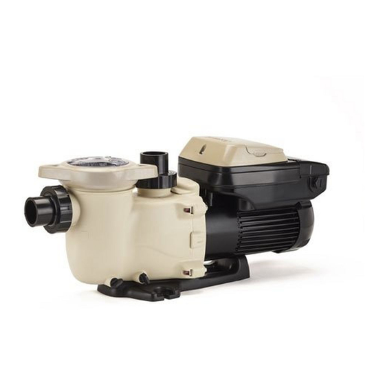
2. General Information 2.1. Introduction This manual contains information for the proper installation and operation of the Jacuzzi 1.65 THP variable speed pump. The instructions in this manual MUST be followed precisely. 2.2. Product Dimensions 3. Energy Efficiency Overview The energy consumed by a pool pump is measured in terms of Watts (W) or Kilowatts (kW). The 1.65 THP variable speed pump displays power consumption in Watts. -
Page 8: Installation And Wiring
It is recommended you filter (“turnover”) all the water in the pool at least once every 24 hours. Check with local requirements for the minimum turnover rate. Running the pump at a lower speed may require running the pump for a longer period of time in order to meet the turnover requirements for proper sanitation. -
Page 9: Plumbing
WARNING – Hazardous Pressure. Pumps, filters, and other equipment/ components of a swimming pool filtration system operate under pressure. Incorrectly installed and/or improperly tested filtration equipment and/or components may fail resulting in severe personal injury or death. 4.4. Plumbing Use PTFE tape to seal threaded connections on molded plastic components. All plastic fittings must be new or thoroughly cleaned before use. -
Page 10: Wiring
4.9. Wiring WARNING – All electrical wiring MUST conform to local codes, regulations, and National Electric Code (NEC) Pump MUST be permanently connected to circuit. If other lights or appliances are also on the same circuit, be sure to add their amp loads before calculating wire and circuit breaker sizes. Use the circuit breaker as the master On-Off switch. -
Page 11: Interface Wall Mounting
4.12. Interface Wall Mounting The interface can also be wall mounted using the parts supplied in the optional wall mount kit using the following procedure. 1. TURN OFF THE ELECTRICAL POWER AT THE CIRCUIT BREAKER. Loosen the two screws securing the user interface to the motor drive and remove the user interface. (Figure 4.12-1) Disconnect the short cable that extends out from the motor drive to the user interface. - Page 12 Figure 4.12-3: Wall Mounting the Interface Page 12 of 32 IS2303VSP3J Rev-A...
-
Page 13: Installation Procedure
4.13. Installation Procedure Please review sections 4.1 through 4.12 before continuing with this section. 1. TURN OFF THE ELECTRICAL POWER AT THE CIRCUIT BREAKER. Loosen the three screws securing the wiring compartment cover and remove the cover to gain access to the drive wiring compartment. -
Page 14: Hayward Automation Control Wiring (Optional, For Remote Control Of Pump Speed)
5.2. Hayward Automation Control Wiring (Optional, for remote control of pump speed) Note: For software compatible Hayward controls only. Existing user interface wiring connection (if present) should be unplugged and second terminal block connector should be used to make wiring connections shown below. Figure 5.2-1 This pump can communicate with and be controlled by Hayward pool controllers such as OmniLogic®, ProLogic®, E- Command®... -
Page 15: External Relay Speed Control Wiring (Optional, For Remote Selection Of Pump Speed)
DIP SWITCH STATUS PUMP ADDRESS Pool Filter Aux 1 / Spa Filter Aux 2 Aux 3 Aux 4 Aux 5 Aux 6 Aux 7 Aux 8 Aux 9 Aux 10 Aux 11 Aux 12 Aux 13 Aux 14 Lights Button 5.3. -
Page 16: Wall Mounted Digital Control Interface Wiring (Optional)
This pump can be controlled by third party pool controllers that are not software compatible using relay contacts to select the speeds set in the Timer Menu (see section 6.7). In addition to this section you may also consult the applicable pool control installation manual for electrical connection details. -
Page 17: Startup & Operation
Connection wire must be rated for a minimum of 300V. Switch must be latching type; pump is stopped when circuit is closed. Inputs are rated to accept a low voltage supply of 18-30 VAC, 9-30 VDC, 50/60 Hz. The “+12V” and “COM” terminals may be used as a low voltage supply, however these terminals also supply power to the user interface , so care must be taken when connecting to these terminals to ensure proper operation of user interface. -
Page 18: User Interface Summary
Fill strainer housing with water to suction pipe level. If water leakage occurs from anywhere on the pump or filter, DO NOT start the pump. If no leakage occurs, stand at least 10 feet from pump and/or filter and proceed with starting the pump. -
Page 19: Menu Outline
Speed 2: 1725 rpm Speed 3: 2300 rpm Speed 4: 2875 rpm Menu/navigation buttons: The MENU button will scroll through the setup menus when pressed. The < and > arrow buttons are used to move between displays and to select parameters to edit, and the + and - arrow buttons are used to change parameters. -
Page 20: Initial Startup
6.5. Initial startup After plumbing and wiring are complete, the variable speed drive must be configured prior to use. When power is applied to the drive for the first time, the following informational screens are displayed. Screen Comments Thursday 1:27p 1725rpm 380 Watts Timer 1 timer... - Page 21 Select pump prime duration < > Prime Duration Move to next menu item 8:00 minutes Note: User may set the pump to prime at the maximum allowed speed for 0-15 minutes in 30 second increments. Select Stand Alone or Relay Control Remote Control Mode <...
-
Page 22: Timer Menu
Use to set selected password character System Locked < > Move to next password character Password: 0___ Note: When password protection is enabled and the timeout has elapsed, the user will be prompted to enter the password to unlock the display when any of the display buttons (other than Stop/Resume) are selected. The user may use Stop/Resume to stop the pump and resume normal operation without having to enter the password. -
Page 23: Preset Speed Setup Menu
Use to choose days of operation for timer Choose Days < > Move to next menu item 7D 7 days a week Note: When start/stop times are set to be the same, the timer is deactivated. Each timer can be set to run on specific days of the week. -
Page 24: Diagnostic Menu
6.9. Diagnostic Menu Buttons Screen Used Comments < > Use > to enter Diagnostic Menu Diagnostic Menu and toggle between displays Press > to enter Press > to view next item Displays firmware version of the display PCB. Display Revision 2.00 Displays motor drive serial number. -
Page 25: Quick Clean
Clean strainer basket regularly. Do NOT strike basket. Inspect cover gasket regularly and replace as necessary. Jacuzzi pumps have self-lubricating motor bearings and shaft seals. No lubrication is necessary. Keep motor clean. Keep motor air vents free of obstructions to avoid damage. Do NOT use water to hose off motor. -
Page 26: Storing Pump For Winterization
Keep motor dry and covered during storage. To avoid condensation/corrosion problems, do NOT cover or wrap pump with plastic film or bags. 8.1. Storing Pump For Winterization WARNING – To avoid dangerous or fatal electrical shock hazard, turn OFF power to motor before draining pump. -
Page 27: Replacing The Impeller And Diffuser
9.5. Replacing the Impeller and Diffuser 11. Screw the impeller onto the motor shaft in a clockwise direction. Tighten snugly by holding motor shaft with wrench as noted in step #3. 12. Place the diffuser over the impeller and onto the seal plate, aligning the three (3) pins with the matching holes in the seal plate. -
Page 28: Parts Listing
10.2. Parts Listing Ref. Part No. Description Qty. SPX2300DLSDB Strainer Cover Kit (Includes Strainer Cover, Lock-Ring & O-Ring) SPX2300Z4 Strainer Cover O-Ring SPX2300M Strainer Basket SPX2300AALB Pump Strainer Housing with Drain Plugs SPX4000FG Drain Plug with O-Ring SPX2700ZPAK Hardware Pack (Incl. 4 Housing Bolts, Seal-Plate Spacers & Square Nuts) SPX2300Z3PAK3 Diffuser Screws (3 Pack) SX220Z2... -
Page 29: Troubleshooting
11. Troubleshooting 11.1. General Problems Motor Will NOT Start: Make sure the terminal board connections agree with the wiring diagram on the pump data plate label. Be sure the pump is wired for the available field supply voltage. Check for and correct any improper or loose wiring connections; open switches or relays; tripped circuit breakers, or blown fuses. -
Page 30: Check System Messages
Noisy Pump: Air leak in suction piping, cavitations caused by restricted or undersized suction line or leak at any joint, low water level in pool, and unrestricted discharge return lines. Correct the suction condition or throttle return lines, if practical. -
Page 31: Warranty
12. Warranty 12.1. For warranty information please visit jacuzzipool.com 13. Product Registration DATE OF INSTALLATION ____________________ INITIAL PRESSURE GAUGE READING (CLEAN FILTER) _______________________ PUMP MODEL __________________ *Retain this Warranty Certificate in a safe and convenient location for your records FCC Compliance Statement: This device complies with part 15 of the FCC rules. - Page 32 JACUZZI is a registered trademark of Jacuzzi Inc. 2020 Jacuzzi Inc. All rights reserved.
Need help?
Do you have a question about the JVS165S and is the answer not in the manual?
Questions and answers
Display reads filter low timer will run in 15 hours. What do I do?
If your Jacuzzi JVS165S displays "filter low timer will run in 15 hours," it means the programmed "Filter Low" timer is set to start in 15 hours. No action is needed unless you want to change the timer settings. To adjust the timer, enter the programming menu and modify the start time, stop time, or days of operation as desired.
This answer is automatically generated
How many gpm can it deliver
How to set a speed to run 24 hours
My panel screen says "Keypad Failed - Key error 68" and the system has stopped working. I have tried to switch off power at the breaker and it remains an error.
I have this pump and the led screen is off and the pump is not working. There is power to the pump. What can I do to trouble shoot it?