
Subscribe to Our Youtube Channel
Related Manuals for O.S. engine GT120THU


Summary of Contents for O.S. engine GT120THU
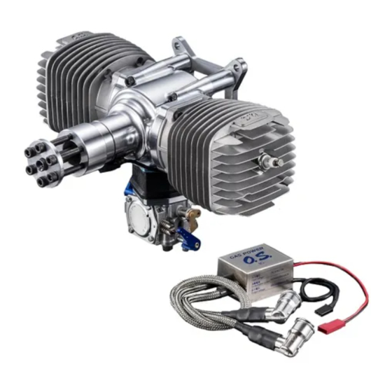
- Page 1 2-stroke gasoline engine for UAV GT120THU Maintenance manual Ver.1.03 2020.OCT.26 O.S. ENGINES MFG. CO., LTD.
-
Page 2: Table Of Contents
Content 1. ABOUT THIS MANUAL ………………………………………………………………………………………………………… 3 2. SAFETY INSTRUCTIONS AND WARNINGS …………………………………………………………………………… 3 3. OPERATION INSTRUCTION AND WARNINGS ……………………………………………………………………… 4 4. PERIODICAL INSPECTION AND MAINTENANCE …………………………………………………………………… 5 (1) Inspection after 25-hour flight (2) Inspection after 50-hour flight (3) Inspection after 100-hour flight 5. - Page 3 (3) Replacing the fuel filter (4) Replacing the fuel tubes 8. EXPLODED VIEW…………………………………………………………………………………………………………………… 17 9. PARTS LIST ………………………………………………………………………………………………………………………… 18 2 / 20...
-
Page 4: About This Manual
1. ABOUT THIS MANUAL The ‘GT120THU maintenance manual’ explains about periodic inspection and maintenance of GT120THU, and about repair when it has an operation failure. It is of vital importance, before maintenance of the engine, to read this manual and adhere to the advice contained herein. -
Page 5: Operation Instruction And Warnings
④ Mount the engine in the aircraft surely following the manufacturer’s instruction. ⑤ Keep unauthorized people away from the engine more than 30 meters before starting it, also do not allow them coming close to a running engine, or there is a possibility of injury. ⑥... -
Page 6: Periodical Inspection And Maintenance
(7) Keep your own memo to remind you how to re-assemble the engine as it was in case the “5. Exploded view” does not help you assembling the engine. (8) Clean the dirt and old oil from the engine parts after disassembling, also remove the liquid gasket which has applied on joint parts. -
Page 7: Inspection After 25-Hour Flight (2) Inspection After 50-Hour Flight (3) Inspection After 100-Hour Flight 5.
④ Check the air cleaner ⑤ Check the plug cap and high-tension cord ⑥ Check the spark plug ⑦ Check the throttle linkage and the chock linkage ⑧ Check the throttle servo and the choke servo ⑨ Check all the screws. ⑩... - Page 8 In case you find large dents and losses of the cooling fins, replace the damaged parts. Remove the foreign objects between the fins if there are. Unusual oil on the surface of the engine often tells a crack on the surface. Replace the part if it is damaged.
- Page 9 (4) Inspection of the air filter ①Check for the damages on the air filter: cracks, tears, wears, deformation, and deterioration. Replace the air filter set in case of any damage. ②Remove visible foreign objects from the surface of the air filter with fingers. Do not use compressed air otherwise the air filter will get damage.
- Page 10 ⑤For general information of the spark plug, visit the homepage of the manufacturer. http://www.ngk-sparkplugs.jp/english/index.html ⑥For further information other than the above, visit the following homepage and refer to Advisory Circular 43. 13-1B, 8-15~17. https://www.faa.gov/documentLibrary/media/Advisory_Circular/AC_43.13-1B_w-chg1.pdf ⑦Re-install the spark plug after the inspection. The fastening torque is 12N・m. (7) Inspection of the throttle linkage and the choke linkage ①Check for damages on the throttle arm, the choke arm, the servo horns, the link rods, the ball links, and the linkage balls (missing, crack, scratch, and deformation).
-
Page 11: Inspection After Every 50 Hours Of Operating Time
The cable between the starter switch SSW-100 and the power source The cable between the generator OGA-200 and the regulate rectifier ORF-200 The cable between the regulate rectifier ORF-200 and the power supply destination The cable between the throttle servo and the receiver The cable between the choke servo and the receiver Check for damage on the connectors of the above: loosening, scratch, deformation, disconnection. -
Page 12: Inspection After Every 100-Hour Of Operating Time
i) Measure the resistance between each three of the connectors, which were disconnected in the above process. ii) In case the average of the phase-to phase resistance measured is 65mΩ±5mΩ, and the deviation is 10mΩ or more, replace the generator. iii) Connect the cables of the generator after inspection or replacement. -
Page 13: ②Inspection And Maintenance Of The Pistons
WARNING When you wash the part with gasoline or kerosene, carry out the work only outdoors or in well ventilated area away from any source of fire to prevent a fire. iii) Remove the carbon sticking to the combustion chamber and the exhaust port. iv) Check the cylinder inner wall for vertical scoring. -
Page 14: ③Inspection And Maintenance Of The Piston Ring
Note 2: The piston is barrel shaped. Do not use a standard micrometer to measure the diameter precisely. Use a blade micrometer. viii) Measure the inner diameter of the piston pin hole (Fig. 11) with an internal caliper gauge. Replace the piston in case the measured inner diameter is more than φ9.140mm. Note: Measure the piston pin hole at both ends vertically and horizontally. -
Page 15: ⑥Inspection And Maintenance Of The Ball Bearings
iii) Check the balancing of the crankshaft using a dial indicator (see Fig.13). If the value is more than 0.100, replace the crankshaft assembly. iv) Measure the big end of the connecting rod our of round with a dial indicator. In case the value is more than 0.120, replace the crankshaft assembly. -
Page 16: ⑧Inspection And Maintenance Of The Generator
in order at which they were minding the front side and the back side. Fastening torque of the four screws is 0.8N・m. Remove the 4 screws, Plate 2, Sheet 3, and 4 (See Fig.15). Check Sheet 3 and 4 (Fig.15) for any deformation and hardening. -
Page 17: ⑩Inspection And Maintenance Of The Starter Gears
⑩Inspection and maintenance of the starter gears Remove the gears from the engine. Wash the gears with kerosene or gasoline. Check the gears for damages or uneven wear of the teeth. Replace the gears if there are damages and uneven wears. WARNING When you wash the parts with gasoline or kerosene, carry out the work only outdoors or in well ventilated area away from any source of fire to prevent a fire. - Page 18 7. EXPLODED VIEW 17 / 20...
- Page 19 8. PARTS LIST 名称 備考/Note № Code Name ナット M10X1.0 締付トルク/ Tightening 79850100 M10X1.0 Torque 44N・m キャップスクリュー M3X6(10 イリ) 締付トルク/ Fastening Torque 79871109 CAP SCREW M3X6(10/SET) 1.1N・m ファンシャフト 4AA08000 FAN SHAF ドライブプーリ 3G63 4AA70010 DRIVE PULLEY 3G63 テーパーコレット 29708100 TAPER COLLET キャップスクリュー...
- Page 20 ナット M12X1.75LH 締付トルク/ Fastening Torque 79850121 NUT M12X1.75LH 44N・m スタータ-モータ- 4AA07140 STARTER MOTOR 4AA07410 O-リング (P15-FKM) O-RING (P15-FKM) スターターピニオンギア 4AA07190 STARTER PINION GEAR キャップスクリュー M4X15(10 イリ) 締付トルク/ Fastening Torque 79871415 CAP SCREW M4X15(10/SET) 3.6N・m 平ワッシャ 6.0(10 イリ) 79872060 WASHER 6.0(10/SET) スターターミドルギア...
- Page 21 71669000 SPARK PLUG CM-6 キャブ及びリードガスケット セット 4AA15000 CAB.& REED GASKET SET リードバルブ 4AB18000 REED VALVE キャブレターインシュレータ- 4AA82000 CARBURETOR INSULATOR GT120THU リペアキット HS-324A 4AB82000 REPAIR KIT HS-324A キャップスクリュー M5X40(10 イリ) 締付トルク/Torque 4.0N・m 79871540 CAP SCREW M5X40(10/SET) キャブレター HS-324A 4AB81000 CARBURETOR HS-324A スロットルアーム...
Need help?
Do you have a question about the GT120THU and is the answer not in the manual?
Questions and answers