
Related Manuals for O.S. engine GF40U-FI


Summary of Contents for O.S. engine GF40U-FI
- Page 1 4 stroke gasoline engine for UAV GF40U-FI With EC11 (ECU) INSTRUCTION MANUAL version 2.46E 2021.08.01 O.S. ENGINES MFG. CO., LTD.
- Page 2 About the engine ・The engine is equipped with electronic fuel injection system to correspond to environmental changes during a long flight. ・This is a four stroke gasoline engine, but runs on a premixed gasoline/2-stroke engine oil. ・Use high quality commercially available 2-stroke engine oil. ・Follow the oil manufacturer's recommedation concerning the mixture ratio of gasoline and oil.
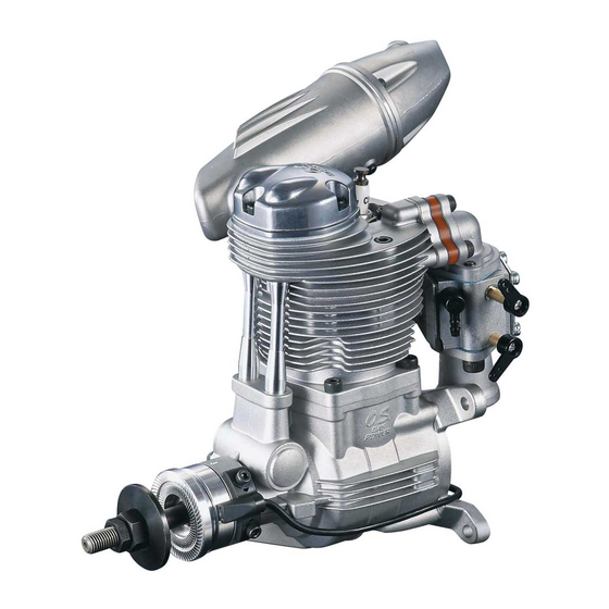
- Page 3 Names of the parts 1. Rocker cover 2. Cylinder head 3. Drive pulley 4. Drive hub 5. Propeller washer 6. Propeller nut 7. Lock nut 8. Crankshaft 9. Driven pulley 10. Intake manifold 11. Cylinder 12. Connector (Injector) 13. Intake air temperature sensor 14....
- Page 4 Names of the parts 23. Injector 24. Throttle valve 25. Injector coupler 26. Manifold pressure sensor 27. Throttle servo 28. Throttle linkage rod 29. Spark plug (CM-6) 30. Cylinder head temperature sensor 31. F-6040 Silencer 32. Generator mount 33. Reinforcement beam 34....
- Page 5 Names of the parts 33. Engine control unit (ECU) 34. ECU connector [CN1] 35. ECU connector [CN2] 36. Status display LED 37. Fuel pump unit 38. Fuel pressure sensor unit 39. Pressure release valve...
- Page 6 Accessories 【Igniter】 Model:IG-08A ・The red connector is a power connector. Supply DC6V~12.6V (MAX1A) for operation. The ignitor requires a separate power source from that of the ECU. Install a power switch outsidfe of a fuselage between Ignitor and power source for safety. ・Connect the black connector to Ignition signal cable of ECU 【Spark plug】...
- Page 7 Accessories 【CAN communication code】 ・the connector for CAN communication...
- Page 8 Standard screw tightening torque ■Cap screw (Hex socket head bolts) screw size N・m M2.6 M3.0 M4.0 M5.0 ※ Follow the above tightning torque unless otherwise specified.
- Page 9 Installation Standoff mount Standoff mount Firewall ・Drill holes as shown above and bolt the engine to the firewall with standoff mounts and M5 bolts. ・Use standoff mounts with 18mm or more outer diameter made of A2017 aluminum or stronger material. ・Use 25mm in length standoff mounts to be able to detatch the injector connector, to space the engine from the fire wall.
- Page 10 Installation Mounting plate (R) Mounting plate(R) Standoff mount Engine bracket M5x20 Bolt ・Attach Mounting plate(R) to the Standoff mounts with M5x20 cap screws. ・There are two types of Engine brackets: Engine bracket A and B are different in direction of Engine support bolts.
- Page 11 Installation Engine support bolt Engine support bolt Add the pair of Nord-Lock Washers to the support bolt. Check this step very carefully. The key faces on inner surface, and radial teeth on the outer suraface. ・Fit the engine to four Engine brackets simultaneously. ・Fasten the four engine support bolts only hand tight at first to align the engine.
-
Page 12: Fuel Delivery
Installation Fuel delivery Hose clamp Fuel filter Fuel pump unit pressure sensor Pressure release valve Fuel tank Return hose Fuel pressure (not included in this set) Connect to engine sensor unit ①Between the Fuel pump unit and Fuel pressure sensor unit ②Between the Fuel pressure sensor unit and Injector coupler ・Connect the Fuel pump unit and the Fuel pressure sensor unit close to the Fuel tank. - Page 13 Installation Fuel pressure sensor unit Hose clamp Pressure release valve Hexagon head Valve holder ・The Pressure sensor works both from A to B and B to A. Decide the mounting direction according to your fuselage layout. Apply Hose clamps to both sides of the Pressure sensor. ・To change the direction of Pressure release valve nipple, loosen the Hexagon head with an 8mm wrench.
- Page 14 Installation Injector coupler Hose clamp Be sure to use [Code No. 28382303 FLUORINE (ETFE) RESIN TUBING (2m)] . From fuel pressure sensor unit ・Connect the tube from the Fuel pressure sensor unit to the Injector joint nipple. Use a Hose clamp. It is a must.
- Page 15 Installation Generator Lower Right side left side ・The position of the generator (OGA-100A) is choosable from the three positions shown above. ・Mount the Generator after mounting the engine. Use four screw holes for each depending on the mounting position. M4x25 Bolt M4x30 Bolt 15mm Spacer 4.5mm Spacer...
- Page 16 Installation 1.Remove the pair of front bolts (M4 x 15) on the generator mount, where you intend to fit the Generator. There bolts are unnecessary in case the Generator is fit. 2. Bolt the Generator support (R) to Mounting plate(F) together with 15mm Spacers using M4x25 Bolts.
- Page 17 Engine control unit (ECU) TO FUEL PUMP UNIT & FUEL SENSOR UNIT Connect to engine Connect to engine [A] Wiring harness A (Sensor and Communication section) {CN1} ・ Throttle signal input (PWM VIH=2.6V,VIL=0.4V,MAX5.5V) ・ Fuel trim signal input (PWM VIH=2.6V,VIL=0.4V,MAX5.5V) ・...
- Page 18 Engine control unit (ECU) ・ To be connected to a receiver or throttle signal cable from flight controller. Specification PWM signal Set the travel width so that the PWM signal width is 1100 μs or less on the throttle closed side and the PWM signal width is 1900 μs or more on the throttle opening side.
- Page 19 Engine control unit (ECU) ・To be connected to Crankshaft rotation sensor. Specification Hall-effect switch. [BR:Signal / R:DC+5V / BR-W:GND] Crankshaft rotation sensor ・the connector for CAN communication Specification SMP-04C-BC [R:DC+5V / W:Signal(High) / G:Signal(Low) /B:GND] CAN communication ・Supply power. Specification DC10V~17V (MAX 1.5A) [R:Power supply /...
- Page 20 Engine control unit (ECU) ・To be connected to the rotation signal input cable of Igniter. Specification [BR:Signal / Y:GND] Ignition signal ・To be connected to Fuel pump. Specification Extension cord [R:DC+12V / B:GND] Fuel pump ・To be connected to Fuel pressure sensor. Specification Extension cord [R-W:DC+5V /...
-
Page 21: Starting The Engine
Operation Starting the engine 【1】 Fill the fuel tank with fuel before turning on the switches of the ECU and the Igniter. 【2】 If there are air bubbles in the tube between the fuel tank and the fuel pump unit after filling up the fuel tank, open the pressure release valve and eiminate the air bubbles. - Page 22 Operation ・the followings are display LED message's meaning. Power LED LED 1 LED2 LED3 Operation status LED engine start mode Off Blink engine operation Blink Blink Blink On (note 1.) fuel pressure abnormal Blink Off at the same time, a buzzer sounds (pressure low) engine stop at the same time, a buzzer sounds...
-
Page 23: Stopping The Engine
Operation Stopping the engine 【1】 Turn off the Ignitor switch to stop the engine. ・Fuel injection cut, throttle cut, and ignition cut functions to stop the engine have not been set yet in this prototype. 【2】 The ECU stops the fuel pump and emits Beep sound intermittently when it detects engine stop. 【3】... -
Page 24: Mounting And Dismounting
Mounting & Dismounting Mounting & Dismounting ・When the fuel tubes are disconnected, open the Pressure release valve and release the residual pressure in the fuel system. ・Remove the four engine support bolts shown below. Disconnect the cable connectors and the fuel tubes before removing the bolts. - Page 25 Mounting & Dismounting How to tighten the screws ・When the Mounting plate(F) and the Engine mount are detached and are attached again, follow the procedures below to avoid giving uneven tension to the Reinforcement beams. 1. Loosen the two bolts, which are connecting the Generator mount and the Engine crankcase to make it possible to move the Generator mount.
- Page 26 Engine parts list ■ENGINE PARTS LIST / GF40U-FI ( 1/3 ) Code No. Description 4AD01000 CRANKCASE GF40U 74002A20 ROTATION SENSOR IG-10 74002321 ROTATION SENSOR FIXING SCREW (2pcs.) 29431000 BALL BEARING(F) 4AD30000 BALL BEARING(R) GF40U 45231100 CAMSHAFT BEARING (1pcs.) 4AD02000 CRANKSHAFT GF40U...
- Page 27 Engine parts list ■ENGINE PARTS LIST / GF40U-FI ( 2/3 ) Code No. Description 4AD84014 INJECTOR WIRE HARNESS 4AD84005 INJECTOR SPACER (2pcs.) 4AD83300 INJECTOR COUPLER GF40U 4AD81950 FUEL INLET (1set) 4AD81100 THROTTLE BODY GF40U 4AD81950 FUEL INLET (1set) 54056014 ST-02 TEMPERATURE SENSOR (1pcs.)
- Page 28 Engine parts list ■ENGINE PARTS LIST / GF40U-FI ( 3/3 ) Code No. Description 75001013 SERIAL SIGNAL CONVERTER 75000206 CAN COMMUNICATION CORD 75003201 EC-11 ECU 75001009 PUMP CONNECTION CORD (50cm) 74002F10 IGNITION MODULE (IG-08A) 54056001 SOCKET WRENCH FOR TEMPERATURE SENSOR...
- Page 30 Engine parts list EC-11 ENGINE CONTROL UNIT ECU WIRE HARNESS (A) EC-11 POWER SUPPLY CORD EC-11 CAN COMMUNICATION CODE ECU WIRE HARNESS (B) EC-11 SERIAL SIGNAL CONVERTER...
- Page 31 Engine parts list PM-02 FUEL PUMP UNIT SP-01 FUEL PRESSURE SENSOR UNIT...
- Page 32 Engine parts list PUMP CONNECTION CORD (50cm) IGNITION MODULE (IG-08A) SOCKET WRENCH FOR TEMPERATURE SENSOR SPARK PLUG CM-6(NGK) HOSE CLIP 6 (5pcs.) GASOLINE FUEL FILTER S NON-BUBBLE WEIGHT S CONECTOR LOCK (5pcs.) FLUORINE(ETFE) RESIN TUBING (2m) (EIGHTRON Flexible Fluorine (ETFE) Resin Tubing Clear made by HAKKO CORPORATION / JAPAN )
- Page 33 Engine parts list VALVE ADJUSTING TOOL KIT GF...
- Page 34 Demantions Unit : mm Unit : mm...
- Page 35 Demantions Unit : mm...
- Page 36 MEMO...
Need help?
Do you have a question about the GF40U-FI and is the answer not in the manual?
Questions and answers