Table of Contents
Advertisement
It is of vital importance, before attempting to
operate your engine, to read the general
'SAFETY INSTRUCTIONS AND WARNINGS'
section on pages 2-6 of this booklet and to strictly
adhere to the advice contained therein.
Also, please study the entire contents of this
instruction manual, so as to familiarize yourself
with the controls and other features of the
engine.
Keep these instructions in a safe place so that
you may readily refer to them whenever
necessary.
It is suggested that any instructions supplied
with the aircraft, radio control equipment, etc.,
are accessible for checking at the same time.
Advertisement
Table of Contents

Related Manuals for O.S. engine FS-52S


Summary of Contents for O.S. engine FS-52S
- Page 1 It is of vital importance, before attempting to operate your engine, to read the general 'SAFETY INSTRUCTIONS AND WARNINGS' section on pages 2-6 of this booklet and to strictly adhere to the advice contained therein. Also, please study the entire contents of this instruction manual, so as to familiarize yourself with the controls and other features of the engine.
-
Page 2: Table Of Contents
CONTENTS SAFETY INSTRUCTIONS AND WARNINGS RUNNING -IN ABOUT YOUR O.S. ENGINE IDLING MIXTURE ADJUSTMENT INTRODUCTION,BASIC ENGINE PARTS VALVE ADJUSTING INSTALLATION CARE AND MAINTENANCE EXHAUST HEADER PIPE AND SILENCER, ENGINE EXPLODED VIEW THROTTLE LINKAGE, NEEDLE-VALVE EXTENSION ENGINE PARTS LIST PROPELLERS, FUEL... -
Page 3: Safety Instructions And Warnings About Your O.s. Engine
As owner, you, alone, are responsible for the safe operation of your engine, so act with discretion and care at all times. If at some future date, your O.S. engine is acquired by another person, we would respectfully request that these instructions are also passed on to its new owner. - Page 4 WARNINGS • Never touch, or allow any object to come • Model engine fuel is also highly flammable. Keep it away from open flame, into contact with, the rotating excessive heat, sources of sparks, or propeller and do not crouch anything else which might over the engine when it is ignite it.
- Page 5 NOTES • • This engine was designed for model If you remove the glowplug from the engine aircraft. Do not attempt to use it for any and check its condition by connecting the other purpose. battery leads to it, do not hold the plug with bare fingers.Use an appropriate tool or a •...
- Page 6 NOTES • Always check the tightness of the propeller • Discard any propeller which has become nut and retighten it, if necessary, before split, cracked, nicked or otherwise rendered restarting the engine, particularly in the unsafe. Never attempt to repair such a case of four-stroke-cycle engines.
- Page 7 NOTES • • Adjust the throttle linkage so that the engine For their safety, keep all onlookers stops when the throttle stick and trim lever (especially small children) well back (at on the transmitter are fully retarded. least 20 feet or 6 meters) when preparing Alternatively, the engine may be stopped by your model for flight.
-
Page 8: Introduction,Basic Engine Parts
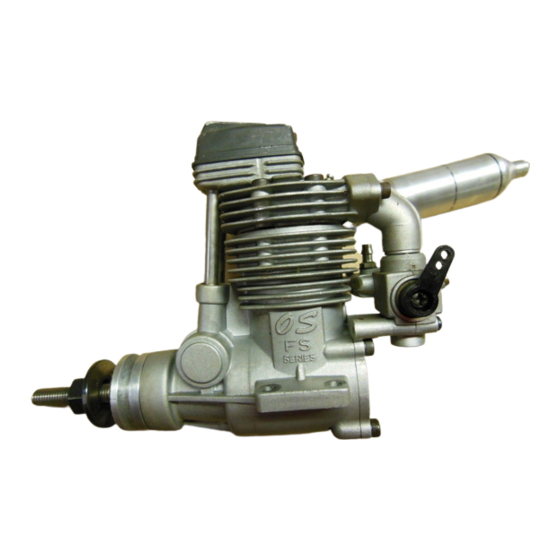
One of the latter is this new FS- 52S model. Closely resembling the FS-48S externally, the FS-52S combines increased performance and improved durability at virtually no increase in overall dimensions or weight. Drive Hub INSTALLING THE GLOWPLUG... -
Page 9: Installation
How to fasten the mounting screws. INSTALLATION Installation in the model Tighten second nut firmly down onto first nut. O.S. radial motor mount A typical method of beam (Available as an optional extra part. 3.5mm steel nuts mounting is shown below,left. Tighten this nut first. -
Page 10: Exhaust Header Pipe And Silencer
EXHAUST HEADER PIPE & SILENCER THROTTLE LINKAGE Before connecting the throttle to the servo, make sure Fit these in the following sequence. that the throttle arm and linkage safely clear any Screw the header pipe into the cylinder head until it adjacent part of the airframe structure, etc., as the bottoms, then unscrew sufficiently to achieve the throttle is opened and closed. -
Page 11: Propellers, Fuel
PROPELLERS The choice of propeller depends on the design and The FS-52S is should be operated on a methanol weight of the aircraft and on the type of flying in which based fuel containing not less than 18% castor-oil, or you will be engaged. -
Page 12: Glowplug
GLOWPLUG • Install a plug suitable for the engine. • The FS-52S is supplied with an O.S. Type F glowplug, Use fuel containing a moderate percentage of specially designed for O.S. four-stroke engines. nitromethane unless more is essential for racing events. -
Page 13: Fuel And Pressure Lines
FUEL AND PRESSURE LINES PROPELLER & SPINNER ATTACHMENT There is a risk, particularly with powerful four-stroke Connect suitable lengths of silicone tubing, as illustrated, after installing the engine. engines, of the propeller flying off if the prop nut loosens due to detonation ("knocking") in the Attention to tank height combustion chamber when the engine is operated Muffler to tank pressure line... -
Page 14: Type 40N Carburettor
TYPE 40N CARBURETTOR Intake pipe retaining screws Two adjustable controls are provided on this carburettor. Fuel Inlet They are as follows: • The Needle Valve Rotor Guide screw This is used to establish the fuel/air mixture strength Carburetor retaining screw required for full power when the throttle is fully open. -
Page 15: Starting 14
Close the throttle-arm to within STARTING 15-20°of the fully closed The FS-52S is not fitted with a manual choke control, position and slowly turn the since it has been designed for use with an electric prop "backwards" (clockwise) starter only. -
Page 16: Running -In 15
The recommended procedure is as follows : 8. Now disconnect current to the glowplug and Start and adjust the engine as detailed in the starting gradually close the needle-valve so that the rpm instructions. increases. Make adjustments to the needle in small steps. -
Page 17: Idling Mixture Adjustment 16
Following the initial running-in session, check for Therefore, at this time ,the aircraft should, as far any looseness in the installation due to vibration, as is possible, be flown at an altitude sufficient to then allow the engine a period of moderately rich enable an emergency landing to be safely made if operation in flight. -
Page 18: Valve Adjusting 17
On the other hand, if the engine hesitates before picking up speed or even ceases firing completely, First rotate the Mixture the idling mixture is likely to be too lean. Turn the Control Valve until its slotted head is flush mixture control valve 90°... - Page 19 The kit comes in a plastic case and includes: The standard valve clearance, on both inlet and (Code No.72200060) exhaust valves, is between 0.04mm and 0.10mm(0.0015-0.004 inch), measured between • Feeler gauge 0.04mm valve stem and rocker arm. Use the 0.04mm and •...
- Page 20 ( 2 ) If a clearance is found to be outside either of Insert 0.04mm feeler gauge between valve stem these limits, it should be reset as follows. and rocker-arm and gently turn adjusting screw clockwise until it stops.(Fig.4.) Carefully loosen the locknut on rocker-arm 1/4-1/2 turn with 5mm wrench.
-
Page 21: Care And Maintenance 20
As noted earlier, the FS-52S has its most engine resulting in damage to the internal parts. Also, vulnerable internal parts protected against such attack... - Page 22 of contaminants as much as possible. CARE & MAINTENANCE (continued) Do not leave unused fuel in the engine at the The fuel pump assembly, carburettor/pressure- conclusion of a day's flying. Accepted practice is to regulator and silicone tubing must be cleansed cut off the fuel supply while the engine is still running separately in methanol or glow fuel.
-
Page 23: Engine Exploded View
ENGINE EXPLODED VIEW C.M2.6X12 C.M3X18 3 -2 ( C.M3X12 ) 3 -1 1 -1 1 -2 5 -4 5 -3 6 -4 5 -2 6 -3 6 -2 5 -1 6 -1 0 -1 C.M2.6X7 7 -1 N.+M2.6X19 0 -2 \ -2 \ -1 \ -2... -
Page 24: Engine Parts List
PARTS LIST Description Code No. Screw Set 4 5813 000 Rocker Cover 4 4204 200 Rocker Support Assembly 4 5261 400 Rocker Support 4 5261 410 Rocker Arm Retainer (2pcs.) 4 5761 600 Rocker Arm Assembly (1pair) 4 5261 010 Rocker Arm (1pc.) 4 5261 110 Tappet Adjusting Screw... -
Page 25: View & Parts List
CARBURETOR EXPLODED VIEW & PARTS LIST Description Code No. Throttle Lever Assembly 2 2081 408 1-1 2 2081 313 Throttle Lever Retaining Screw Carburetor Rotor 4 4281 200 4 4281 960 Nozzle Assembly 4 4281 600 Mixture Control Screw Assembly 9 -1 4 6066 319 "O"... -
Page 26: Genuine Parts & Accessories
PARTS & ACCESSORIES Flexible Exhaust Pipes O.S.Glow Plug Exhaust Header Radial Mount Set Pipe 52S(IN-COWL) TYPE F (71913000) (71615009) (72108400) Code.No. Type Length (mm) Exhaust Header Pipe 72108300 1010A Assembly 72108310 1010B (45226000) Long Socket Wrench With Bubble Eliminating Locknut Set for Spinner 1/4"-M5 Plug Grip (71521000) -
Page 27: Three View Drawing
THREE VIEW DRAWING Dimension(mm) Specification Displacement 8.56cc (0.523cu.in.) Bore 23.0mm (0.906in.) Stroke 20.6mm (0.811in.) Practical R.P.M. 2,300 13,000r.p.m. Power output 0.9bhp/12,000r.p.m. Weight 434g (15.31oz.) - Page 28 6-15 3-Chome Imagawa Higashisumiyoshi-ku Osaka 546-0003, Japan TEL. (06) 6702-0225 FAX. (06) 6704-2722 URL : http://www.os-engines.co.jp Copyright 2000 by O.S.Engines Mfg. Co., Ltd. All rights reserved. Printed in Japan. 100101...
Need help?
Do you have a question about the FS-52S and is the answer not in the manual?
Questions and answers