Table of Contents
Advertisement
It is of vital importance, before attempting to
operate your engine,
'SAFETY INSTRUCTIONS AND WARNINGS'
section on pages 2-4 of this booklet and to
strictly adhere to the advice contained therein.
Also, please study the entire contents of this
instruction manual, so as to familiarize
yourself with the controls and other features
of the engine.
Keep these instructions in a safe place so that
you may readily refer to them whenever
necessary.
It is suggested that any instructions supplied
with the aircraft, radio control equipment, etc.,
are accessible for checking at the same time.
CONTENTS
INTRODUCTION, TOOLS AND ACCESSORIES
PROPELLER, FUEL TANK
to read the general
2-4
5
6-7
8-10
10-11
12
13-14
15-18
18-19
19-21
Horizontally-opposed twin-cylinder
overhead-valve four-stroke-cycle
ENGINE EXPLODED VIEWS
ENGINE PARTS LISTS
ENGINE THREE VIEW DRAWINGS
1
22
22
23-25
26
27
28
29
30
Advertisement
Table of Contents

Related Manuals for O.S. engine FT-160


Summary of Contents for O.S. engine FT-160
-
Page 1: Table Of Contents
It is of vital importance, before attempting to operate your engine, to read the general 'SAFETY INSTRUCTIONS AND WARNINGS' section on pages 2-4 of this booklet and to strictly adhere to the advice contained therein. Also, please study the entire contents of this instruction manual, so as to familiarize yourself with the controls and other features of the engine. -
Page 2: Safety Instructions And Warnings About Your O.s. Engine
SAFETY INSTRUCTIONS AND WARNINGS ABOUT YOUR WARNINGS O.S. ENGINE Never touch, or allow any object to come into Remember that your engine is not a " toy ", but a highly contact with, the rotating propeller and do not efficient internal-combustion machine whose power is crouch over the engine when it is running. - Page 3 Use an electric starter for this engine. The wearing of safety glasses is also strongly recommended. Take care that the glow plug clip or battery leads do not come into contact with the propeller. Also check the linkage to the throttle arm. A disconnected linkage could also foul the propeller. After starting the engine, carry out any needle-valve readjustments from a safe position behind the rotating propeller.
-
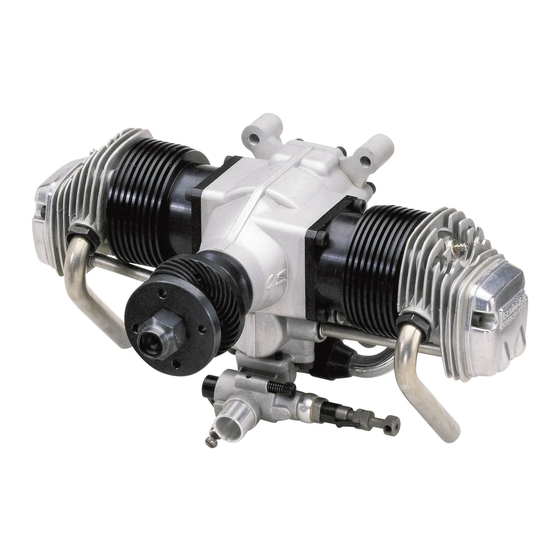
Page 4: Engine Parts Name
Photo. 2 ENGINE PARTS NAME Right (No.2) Cylinder Crankcase Aluminum tube Left (No.1) Cylinder Cylinder Head Glow Plug Rocker Cover Propeller Nut Lock Nut Propeller Washer Drive Hub Exhaust Pipe Carburetor Aluminum tube is not supplied with the engine. Photo. 3 Choke Valve Intake Manifold Fuel Inlet... -
Page 5: Installation
INSTALLATION It is essential that the firewall is strong and rigid (e.g. at Needle-valve extension least 15mm thick) and firmly integrated with the structure of The needle-valve with this engine is designed to incorporate the aircraft. an extension so that, when the engine is enclosed within the fuselage, the needle-valve may be adjusted from the In the interests of scale appearance, the engine should be outside. -
Page 6: Fuel Tank
Carburetor PROPELLER needle-valve throttle lever locations The choice of propeller depends on the design and weight of interchangeable by reversing the carburetor. This can be the aircraft and on the type of flying in which you will be done as follows: engaged. -
Page 7: Glowplugs
GLOWPLUGS The FT-160 is supplied with an O.S. Type F glowplug, When to replace the glowplug specially designed for O.S. four-stroke engines. Apart from when actually burned out, a plug may need to be replaced because it no longer delivers its best performance, The role of the glowplug such as when: With a glowplug engine, ignition is initiated by the application... -
Page 8: Fuel And Lubrication, Starting
Glowplug leads If glowplug leads are extended together as a single cable, The plug leads are fitted with special snap-on connectors use heavier wire, e.g. 2.0 mm multi-strand copper core as that ensure firm contact with O.S. plug. They are a "click" fit supplied for earth lead. - Page 9 Make sure that glowplugs are not connected to the battery. If very strong compression is felt when trying to turn the Do not heat the glowplugs while priming. (Fig.15). propeller counter-clockwise, too much fuel has been drawn into the engine. In this case, do not use force, but release the choke valve and turn the propeller clockwise slowly to Do not connect the battery to eject excess fuel through exhaust pipes.
-
Page 10: Running-In ("Breaking-In")
Adjust the needle-valve RUNNING-IN ("Breaking-in") Abrupt adjustment of the needle-valve may cause the Obtain a 18x6 propeller for running-in. engine to stop, especially when it is new and insufficiently run-in. 1. Running-in on the ground As the speed of the engine does not instantly change with needle-valve readjustment, small movements, with pauses Start the engine between, are necessary to arrive at the optimum setting. - Page 11 Start the engine. Disconnect the glowplugs from the battery. open the throttle fully . Approx 40˚ open from maximum r.p.m. setting. Adjust the neede-valve. Make sure that all 2 cylinders are firing. Close the throttle gradually. The position where the lowest Find the idling position.
-
Page 12: Flight
Adjusting the mixture control valve of the + mark about 1/12 turn (30 ). Normal safe idling speeds are in the region of 2,000 r.p.m.. If the engine hesitates, puffing out Mixture Control Screw a good deal of smoke, before NOTE: picking up to full speed, it is As this is two-cylinder four-stroke-cycle engine, firing... -
Page 13: Valve Clearance Adjustment
VALVE CLEARANCE ADJUSTMENT ALL O.S. four-stroke engines have their valve (tappet) Remove all the glowplugs except the one fitted to the clearances correctly set before they leave the factory. cylinder that you want to check. However, if, after many hours of running time have been logged, a loss of power is detected, or if the engine has to Note: be disassembled or repaired as a result of an accident,... - Page 14 Re-tighten locknut while holding adjusting screw stationary. (Fig.33.) Hold at the screw head. Tighten Locknut. Fig.33 Remove 0.04mm feeler, rotate prop through two revolutions and recheck gap. If clearance is correct, loosen the locknut on the other rocker-arm and repeat steps 1 to 5 above. Finally, replace rocker box cover.
- Page 15 EXPLODED VIEW C.M3x16 C.M4x22 C.M3.5x12 29-1 C.M3.5x10 12-2 C.M3.5x15 12-1 13-1 13-2 C.M3x15 C.M3.5x20 16-2 16-1 16-3 C.M2.6x7 C.M3x8 Type of screw N.+M3x22 C...Cap Screw M...Oval Fillister-Head Screw F...Flat Head Screw N...Round Head Screw S...Set Screw PARTS LIST Code No. Description Code No.
-
Page 16: Carburetor Exploded Views & Parts List
CARBURETOR EXPLODED VIEWS & PARTS LIST S.M3x3 Code No. Description 26381501 Set-screw 24981405 Throttle Lever Assembly 26381501 Set-screw 46481320 Mixture Control Screw Assembly 22781800 "O" Ring (2pcs.) S.M3x3 46481330 Mixture Control Screw Holder Assembly 26381501 Set-screw S.M3x3 46481200 Carburetor Rotor 46281340 Mixture Control Valve Pin 46481310... - Page 17 THREE VIEW DRAWING Specifications Displacement 13.26cc x 2 / 1.218cu.in. x 2 Bore 27.7mm / 1.091in. Stroke 22.0mm / 0.866in. PracticalR.P.M. 2.000-10.000r.p.m. Output Weight 1,100g / 38.8oz. 4 -5.2 Dimensions(mm) 6-15 3-Chome Imagawa Higashisumiyoshi-ku Osaka 546-0003, Japan TEL. (06) 6702-0225 FAX.
Need help?
Do you have a question about the FT-160 and is the answer not in the manual?
Questions and answers