
Related Manuals for GORMAN-RUPP PUMPS PA Seris


Summary of Contents for GORMAN-RUPP PUMPS PA Seris
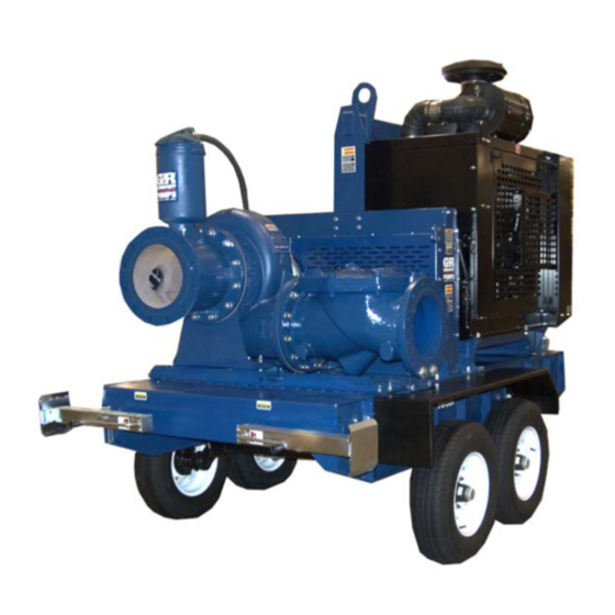
- Page 1 OM-06575-05 July 24, 2012 INSTALLATION, OPERATION, AND MAINTENANCE MANUAL WITH PARTS LIST PA SERIES PUMP MODEL PA12A60-B GORMAN‐RUPP PUMPS www.grpumps.com 2012 Gorman‐Rupp Pumps Printed in U.S.A.
- Page 2 Register your new Gorman‐Rupp pump online at www.grpumps.com Valid serial number and e‐mail address required. RECORD YOUR PUMP MODEL AND SERIAL NUMBER Please record your pump model and serial number in the spaces provided below. Your Gorman‐Rupp distributor needs this information when you require parts or service. Pump Model: Serial Number:...
-
Page 3: Table Of Contents
TABLE OF CONTENTS INTRODUCTION ..........PAGE I - 1 SAFETY ‐... - Page 4 TABLE OF CONTENTS (continued) PARTS LISTS: Pump Model ............PAGE E - 3 Pump Endl Assembly .
-
Page 5: Introduction
OM-06575 PA SERIES INTRODUCTION Thank You for purchasing a Gorman‐Rupp pump. The following are used to alert personnel to proce Read this manual carefully to learn how to safely dures which require special attention, to those install and operate your pump. Failure to do so which could damage equipment, and to those could result in personal injury or damage to the which could be dangerous to personnel:... -
Page 6: Safety - Section A
PA SERIES OM-06575 SAFETY ‐ SECTION A This information applies to Prime Aire sive, or flammable materials which may Series pumps. Gorman‐Rupp has no damage the pump or endanger person control over or particular knowledge of nel as a result of pump failure. the power source which will be used. - Page 7 OM-06575 PA SERIES gaged to be ejected with great force. Al low the pump to cool before servicing. Do not attempt to disengage any part of an overheated pump unit. Vapor pres sure within the pump casing can eject Do not operate the pump against a these parts with great force when they closed discharge valve for long periods are disengaged.
-
Page 8: Installation - Section B
PA SERIES OM-06575 INSTALLATION - SECTION B Review all SAFETY information in Section A. dicated by the arrow on the pump body and on the accompanying decal. Other Since pump installations are seldom identical, this wise, the impeller could become loosened section offers only general recommendations and from the shaft and seriously damage the practices required to inspect, position, and ar... -
Page 9: Mounting
OM-06575 PA SERIES Pump unit weights will vary depending on the place by tightening the flange bolts and/or cou mounting and drive provided. Check the shipping plings. tag on the unit packaging for the actual weight, and Lines near the pump must be independently sup use lifting equipment with appropriate capacity. -
Page 10: Sealing
PA SERIES OM-06575 of the openings in the strainer is at least three or If it is necessary to position inflow close to the suc four times the cross section of the suction line, and tion inlet, install a baffle between the inflow and the that the openings will not permit passage of solids suction inlet at a distance 1‐1/2 times the diameter larger than the solids handling capability of the... -
Page 11: Discharge Lines
OM-06575 PA SERIES Figure 1. Recommended Minimum Suction Line Submergence vs. Velocity DISCHARGE LINES Siphoning If the application involves a high discharge head, gradually close the discharge Do not terminate the discharge line at a level lower throttling valve before stopping the pump. than that of the liquid being pumped unless a si... -
Page 12: Coupled Drives
PA SERIES OM-06575 must be checked and realigned before operation. Before checking alignment, tighten the foundation bolts. The pump casing feet and/or pedestal feet, and the driver mounting bolts should also be tightly secured. When checking alignment, disconnect the power source to ensure that the pump will remain inoperative. -
Page 13: Drive Belt Tensioning
OM-06575 PA SERIES Tighten the belts in accordance with the belt manu One method is through the use of an optional heat facturer's instructions. If the belts are too loose, ed priming chamber, which is available as a facto they will slip; if the belts are too tight, there will be ry‐installed option or as a retrofit kit for most mod... -
Page 14: Operation - Section C
OM-06575 PA SERIES OPERATION - SECTION C Review all SAFETY information in Section A. If rotation is incorrect on a three‐phase motor, have a qualified electrician interchange any two of the three phase wires to change direction. If rotation is Follow the instructions on all tags, labels and incorrect on a single‐phase motor, consult the liter... -
Page 15: Liquid Temperature And Overheating
OM-06575 PA SERIES Liquid Temperature And Overheating flow rate begins to drop. Monitor and record the vacuum suction gauge readings regularly to detect strainer blockage. The maximum liquid temperature for this pump is F (71 C). Do not apply it at a higher operating Never introduce air or steam pressure into the temperature. -
Page 16: Cold Weather Preservation
OM-06575 PA SERIES When pumps are first started, the bearings may been pumping liquids containing a large amount of seem to run at temperatures above normal. Con solids, drain the pump, and flush it thoroughly with tinued operation should bring the temperatures clean water. -
Page 17: Troubleshooting - Section D
OM-06575 PA SERIES TROUBLESHOOTING - SECTION D Review all SAFETY information in Section A. Before attempting to open or service the pump: 1. Familiarize yourself with this manual. 2. Lock out or disconnect the power source to ensure that the pump will remain inoperative. - Page 18 OM-06575 PA SERIES TROUBLE POSSIBLE CAUSE PROBABLE REMEDY Check strainer and clean if neces Strainer clogged. PUMP STOPS OR FAILS TO DELIVER sary. RATED FLOW OR Check and clean check valve. Discharge check valve clogged. PRESSURE (cont.) Suction intake not submerged at Check installation and correct proper level or sump too small.
-
Page 19: Preventive Maintenance
OM-06575 PA SERIES TROUBLE POSSIBLE CAUSE PROBABLE REMEDY BEARINGS RUN Bearing temperature is high, but Check bearing temperature regu TOO HOT within limits. larly to monitor any increase. Low or incorrect lubricant. Check for proper type and level of lubricant. Suction and discharge lines not prop... - Page 20 OM-06575 PA SERIES Preventive Maintenance Schedule Service Interval* Item Daily Weekly Monthly Semi‐ Annually Annually General Condition (Temperature, Unusual Noises or Vibrations, Cracks, Leaks, Loose Hardware, Etc.) Pump Performance (Gauges, Speed, Flow) Bearing Lubrication Seal Lubrication (And Packing Adjustment, If So Equipped) V‐Belts (If So Equipped) Air Release Valve Plunger Rod (If So Equipped) Front Impeller Clearance (Wear Plate)
-
Page 21: Pump Maintenance And Repair - Section E
OM-06575 PA SERIES PUMP MAINTENANCE AND REPAIR - SECTION E MAINTENANCE AND REPAIR OF THE WEARING PARTS OF THE PUMP WILL MAINTAIN PEAK OPERATING PERFORMANCE. STANDARD PERFORMANCE FOR PUMP MODEL PA12A60-B Based on 70 F (21 C) clear water at sea level Contact the Gorman‐Rupp Company to verify per... - Page 22 OM-06575 PA SERIES PARTS PAGE ILLUSTRATION Figure 1. PA12A60-B Pump Model Assembly PAGE E - 2 MAINTENANCE & REPAIR...
- Page 23 OM-06575 PA SERIES PARTS LIST Pump Model PA12A60-B (From S/N 1650474 Up) ITEM PART PART NAME NUMBER PUMP END ASSEMBLY 46133-640 PRIMING CHAMBER ASSEMBLY 46112-709 GASKET 4991G 18000 HEX HEAD CAP SCREW B1413 15991 HEX HEAD CAP SCREW B1416 15991 LOCK WASHER J14 15991 HEX NUT...
- Page 24 OM-06575 PA SERIES ILLUSTRATION SEE FIG. 3 Figure 2. Pump End Assembly PAGE E - 4 MAINTENANCE & REPAIR...
- Page 25 OM-06575 PA SERIES PARTS LIST Pump End Assembly ITEM PART NAME PART ITEM PART NAME PART NUMBER NUMBER PUMP CASING SEE NOTE BELOW ROLLER BEARING 23528-005 IMPLLR/WEAR RING ASSY 46151-022 24110 BEARING CAP 38322-425 10010 AIR VENT S1703 -WEAR RING 4182A 11030 O‐RING 25151-266...
- Page 26 OM-06575 PA SERIES ILLUSTRATION SEE FIG. 2 Figure 3. Pump End Assembly (Cont'd) PAGE E - 6 MAINTENANCE & REPAIR...
- Page 27 OM-06575 PA SERIES PARTS LIST Pump End Assembly (Cont'd) ITEM PART NAME PART ITEM PART NAME PART NUMBER NUMBER PUMP CASING SEE NOTE BELOW ROLLER BEARING 23528-005 IMPLLR/WEAR RING ASSY 46151-022 24110 BEARING CAP 38322-425 10010 AIR VENT S1703 -WEAR RING 4182A 11030 O‐RING 25151-266...
- Page 28 OM-06575 PA SERIES ILLUSTRATION Figure 4. Priming Chamber Assembly PARTS LIST ITEM PART PART NAME NUMBER PRIMING VALVE 26664-007 -ORIFICE BUTTON 26688-021 HEX HD CAPSCREW B0806 15991 LOCKWASHER J08 15991 PRIMING VALVE GASKET 38683-657 19060 PRIMING CHAMBER 38343-020 10000 STRAINER ASSY 46641-222 17000 INDICATES PARTS RECOMMENDED FOR STOCK PAGE E - 8...
- Page 29 OM-06575 PA SERIES ILLUSTRATION IMPELLER WEAR RING NOTE: UNLESS OTHERWISE SPECIFIED, MACHINED SURFACES TO BE 125 RMS. Figure 5. Impeller Assembly Machining Tolerances MAINTENANCE & REPAIR PAGE E - 9...
- Page 30 OM-06575 PA SERIES PUMP AND SEAL DISASSEMBLY 1. Familiarize yourself with this man ual. AND REASSEMBLY 2. Disconnect or lock out the power source to ensure that the pump will Review all SAFETY information in Section A. remain inoperative. Follow the instructions on all tags, label and de 3.
- Page 31 PA SERIES OM-06575 a sling and a suitable lifting device. Remove the Suction Head And Wear Ring Removal hardware (21 and 22) and separate the priming (Figure 2) chamber assembly, baffle (18) and gasket (19) from the pump assembly. Unless replacement of the spool gasket (3, Figure 1) is required, the suction head (49) may be re...
- Page 32 OM-06575 PA SERIES a wood block through the pump discharge and Seal Removal into the impeller vanes. Remove the impeller screw (Figures 2 and 6) and washer (8). Remove the wood block from the This pump is designed with two seals; a primary pump discharge.
- Page 33 PA SERIES OM-06575 is not recommended. These operations flammable. Use them only in a well ven should be performed only in a properly tilated area free from excessive heat, equipped shop by qualified personnel. sparks, and flame. Read and follow all precautions printed on solvent contain...
- Page 34 OM-06575 PA SERIES After the bearings have been installed and allowed to cool, check to ensure that they have not moved away from the shaft shoulders in shrinking. If movement has occurred, use a suitably sized Use caution when handling hot bearings to sleeve and a press to reposition the bearings prevent burns.
- Page 35 PA SERIES OM-06575 gency, carefully wash all metallic parts in fresh cleaning solvent and allow to dry thoroughly. Handle the seal parts with extreme care to prevent Most cleaning solvents are toxic and damage. Be careful not to contaminate precision flammable.
- Page 36 OM-06575 PA SERIES SPRING RETAINER SEAL PLATE IMPELLER SHAFT STATIONARY SLEEVE ELEMENT O‐RING IMPELLER ROTATING SHAFT ELEMENT O‐RINGS BELLOWS SHAFT SLEEVE STATIONARY SEAT IMPELLER SHIMS Figure 6. Seal Assembly PAGE E - 16 MAINTENANCE & REPAIR...
- Page 37 PA SERIES OM-06575 welded to the impeller. Failure to properly install the wear ring and machine and bal ance the impeller assembly can result in premature shaft, seal or bearing failure, or The standard seal is not designed for oper other damage to the pump.
- Page 38 OM-06575 PA SERIES the impeller capscrew (7). Immobilize the shaft and Discharge Check Valve Assembly and secure the the impeller by torquing the capscrew Installation to 225 ft. lbs. (2700 in. lbs. or 31 m. kg.). (Figure 1) The flapper and gasket are the only serviceable Pump Casing Installation parts of the check valve.
- Page 39 PA SERIES OM-06575 ing chamber assembly on the hopper spool (13). quired, remove the vented plug (19) and add SAE Secure the priming chamber assembly with the No. 30 non‐detergent oil through the opening. hardware (21 and 22). Clean and reinstall the vented plug. Do not over‐lu bricate.
- Page 40 For Warranty Information, Please Visit www.grpumps.com/warranty or call: U.S.: 419-755-1280 Canada: 519-631-2870 International: +1-419-755-1352 GORMAN‐RUPP PUMPS...
Need help?
Do you have a question about the PA Seris and is the answer not in the manual?
Questions and answers