Sign In
Upload
Download
Table of Contents
Contents
Add to my manuals
Delete from my manuals
Share
URL of this page:
HTML Link:
Bookmark this page
Add
Manual will be automatically added to "My Manuals"
Print this page
×
Bookmark added
×
Added to my manuals
Manuals
Brands
ATEN Manuals
Switch
CS18208
User manual
ATEN CS18208 User Manual
8/16-port usb 3.0 4k hdmi kvm switch
Hide thumbs
1
2
3
4
Table Of Contents
5
6
7
8
9
10
11
12
13
14
15
16
17
18
19
20
21
22
23
24
25
26
27
28
29
30
31
32
33
34
35
36
37
38
39
40
41
42
43
44
45
46
47
48
49
50
51
52
53
54
55
56
57
58
59
60
61
62
63
64
65
66
67
68
69
70
71
72
73
74
75
76
77
78
79
80
81
82
83
84
85
86
87
88
89
90
91
92
93
94
95
96
97
98
99
100
101
102
103
104
105
106
107
108
109
110
page
of
110
Go
/
110
Contents
Table of Contents
Bookmarks
Table of Contents
EMC Information
Rohs
User Information
Online Registration
Telephone Support
User Notice
Package Contents
Table of Contents
About this Manual
Conventions
Product Information
1 Introduction
Overview
Features
Requirements
Console
Computers
Cables
Operating Systems
Components
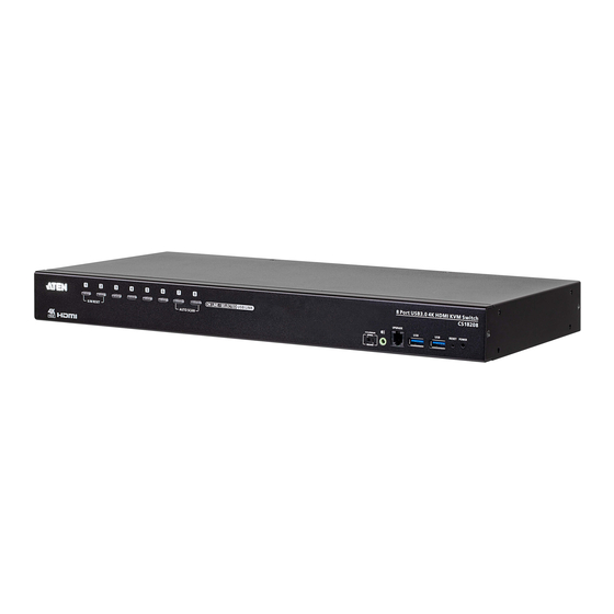
Front View CS18208
Front View CS18216
Rear View CS18208
Rear View CS18216
2 Hardware Setup
Overview
Installation Types
Before You Begin
Stacking and Rack Mounting
Stacking
Rack Mounting - Front
Rack Mounting - Rear
Single Stage Installation
Single Stage Installation Diagram
Two Stage Cascade
Two Stage Installation Diagram
Three Stage Cascade
Three Stage Installation Diagram
Multi-Display Installation
Cable Connections for Multi-Display Installation
Multi-Display Installation Diagram
Grouping Ports into "Vertical" Channels
Channels Diagram
3 Basic Operation
Hot Plugging
Hot Plugging KVM Ports
Hot Plugging Console Ports
Port Selection
Manual Port Switching
Port ID Numbering
Powering off and Restarting
4 OSD Operation
OSD Overview
Manufacturing Number
OSD Login
OSD Hotkey
OSD Main Screen
OSD Main Screen Headings
OSD Navigation
OSD Functions
F1: Go to
F2: List
F3: Set
F4: Admin
F5: Skp
F6: Brc
F7: Scan
F8: Logout
5 Hotkey Operation
Hotkey Port Control
Hotkey Setting Mode
Invoking HSM
Select the Active Port
Auto Scan Mode
Invoking Auto Scan
Skip Mode
Keyboard / Mouse Reset
Hotkey Beeper Control
HSM Hotkey Control
OSD Hotkey Control
Port os Control
Restore Default Values
Video Dynasync
EDID Mode
Mouse Emulation Control
HSM Summary Table
6 Keyboard Emulation
Mac Keyboard
Sun Keyboard
7 RS-232 Operation
Overview
Setup
Hardware Connection
RS-232 Pin Assignments
Console Login - Hyperterminal
RS-232 Commands
Verification
Login
Logout
Open / Close RS-232 Link
Set Baud Rate
Switch Port
Hotkey Setting
OSD Hotkey
USB Reset
Restore Default Settings
Firmware Upgrade
KVM Status
EDID Mode
Broadcast Mode
8 The Firmware Management Utility
Introduction
Downloading the Firmware Upgrade Package
Preparation
Starting the Upgrade
Upgrade Succeeded
Upgrade Failed
Firmware Upgrade Recovery
OSD Configuration Backup/Restore
Backup
Restore
Appendix
Safety Instructions
General
Rack Mounting
Technical Support
International
North America
CS18208 / CS18216 Connection Tables
Specifications
Administrator Login Failure
Factory Default Hotkeys and Settings
Limited Warranty
Advertisement
Quick Links
1
Osd Login
Download this manual
8/16-Port USB 3.0 4K HDMI KVM Switch
CS18208 / CS18216
User Manual
CS18208 / CS18216
8/16-Port USB 3 . 0 4K HDMI KVM Switch
User Manual
www.aten.com
Table of
Contents
Previous
Page
Next
Page
1
2
3
4
5
Advertisement
Table of Contents
Need help?
Do you have a question about the CS18208 and is the answer not in the manual?
Ask a question
Questions and answers
Related Manuals for ATEN CS18208
Switch ATEN KVMP CS1822 User Manual
2/4-port usb3.0 4k hdmi switch (52 pages)
Switch ATEN CS1822 User Manual
2/4-port usb3.0 4k hdmi kvmp switch rs-232 commands (18 pages)
Switch ATEN CS1822 User Manual
2/4-port usb 3.0 4k hdmi kvmp switch (56 pages)
Switch ATEN CS1822 User Manual
2/4-port usb 3.0 4k hdmi kvmp switch (25 pages)
Switch ATEN CS1822 User Manual
2/4-port usb 3.0 4k hdmi kvmp switch (62 pages)
Switch ATEN CS18216 User Manual
8/16-port usb 3.0 4k hdmi kvm switch (110 pages)
Switch ATEN CS1842 User Manual
2/4-port usb 3.0 4k hdmi dual display kvmp switch (76 pages)
Switch ATEN CS1842 User Manual
2/4-port usb 3.0 4k hdmi dual display kvmp switch (88 pages)
Switch ATEN Master View CS-138A User Manual
Aten masterview cs-138a kvm switch: user manual (31 pages)
Switch ATEN CS1742 User Manual
Dual-view kvm switch (55 pages)
Switch ATEN CS176A User Manual
Usb dvi kvmp switch (56 pages)
Switch ATEN CS1708A User Manual
(77 pages)
Switch ATEN CS1768 User Manual
8-port usb dvi kvm switch (86 pages)
Switch ATEN CS1708i User Manual
Kvm on the net (176 pages)
Switch ATEN CS1922M User Manual
2/4-port usb 3.0 4k displayport mst kvmp switch (60 pages)
Switch ATEN CS1953 User Manual
3-port usb-c displayport hybrid kvmp switch (56 pages)
This manual is also suitable for:
Cs18216
Table of Contents
Save PDF
Print
Rename the bookmark
Delete bookmark?
Delete from my manuals?
Login
Sign In
OR
Sign in with Facebook
Sign in with Google
Upload manual
Upload from disk
Upload from URL


Need help?
Do you have a question about the CS18208 and is the answer not in the manual?
Questions and answers