Table of Contents

Related Manuals for ATEN CS1768


Summary of Contents for ATEN CS1768
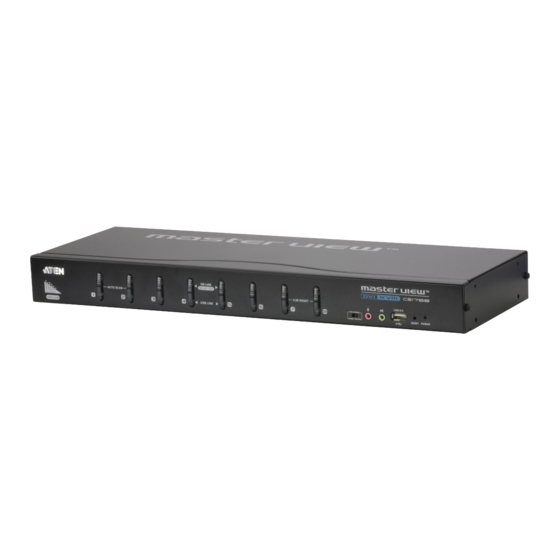
- Page 1 8-port USB DVI KVM Switch CS1768 / CS1788 User Manual www.aten.com...
-
Page 2: Fcc Information
CS1768 / CS1788 User Manual FCC Information This is an FCC Class A product. In a domestic environment this product may cause radio interference in which case the user may be required to take adequate measures. This equipment has been tested and found to comply with the limits for a Class A digital device, pursuant to Part 15 of the FCC Rules. -
Page 3: User Information
CS1768 / CS1788 User Manual User Information Online Registration Be sure to register your product at our online support center: International http://support.aten.com North America http://www.aten-usa.com/product_registration Telephone Support For telephone support, call this number: International 886-2-8692-6959 China 86-10-5255-0110 Japan 81-3-5615-5811 Korea... -
Page 4: Package Contents
© Copyright 2012 ATEN® International Co., Ltd. Manual Date: 2013-01-08 ATEN and the ATEN logo are registered trademarks of ATEN International Co., Ltd. All rights reserved. All other brand names and trademarks are the registered property of their respective owners. -
Page 5: Table Of Contents
CS1768 / CS1788 User Manual Contents FCC Information ..........ii RoHS. - Page 6 CS1768 / CS1788 User Manual 3. Basic Operation Hot Plugging ..........29 Hot Plugging KVM Ports .
- Page 7 North America ......... . 70 CS1768 / CS1788 Connection Tables ......71 Specifications .
-
Page 8: About This Manual
CS1768 / CS1788 User Manual About this Manual This User Manual is provided to help you get the most from your CS1768 / CS1788 system. It covers all aspects of installation, configuration and operation. An overview of the information found in the manual is provided below. -
Page 9: Conventions
For information about all ATEN products and how they can help you connect without limits, visit ATEN on the Web or contact an ATEN Authorized Reseller. Visit ATEN on the Web for a list of locations and telephone numbers: International http://www.aten.com... - Page 10 CS1768 / CS1788 User Manual This Page Intentionally Left Blank...
-
Page 11: Introduction
Introduction Overview The CS1768 / CS1788 is a control unit that allows access and control of up to 8 computers from a single USB keyboard, USB mouse, and monitor (DVI or VGA) console. The CS1768 supports Single Link DVI; the CS1788 supports Dual Link DVI. -
Page 12: Features
– exclusive ATEN technology eliminates boot-up display problems and optimizes resolution when switching between ports Superior video quality – 1920 x 1200 (Single Link DVI – CS1768) / 2560 x 1600 (Dual Link DVI – CS1788); 2048 x 1536 (VGA); DDC2B Supports widescreen resolutions Audio enabled –... - Page 13 1. Introduction Console mouse port emulation/bypass feature supports most mouse drivers and multifunction mice Complete keyboard emulation for error-free booting Mac/Sun keyboard support and emulation** Multilingual OSD supports English, German, Japanese, Traditional Chinese, Simplified Chinese, Spanish, Russian, and French Multilingual keyboard mapping – supports English (US), English (UK), French, German, Japanese, Korean, Traditional Chinese, and Spanish Note: 1.
-
Page 14: Requirements
Type A USB port Microphone and speaker ports (optional) Note: The VGA monitor and VGA card are supported by the CS1768 / CS1788, but are both optional. Refer to Console Monitor Connection Options, page 18 for more information on console and computer... -
Page 15: Cables
2L-7D02UD Link 3.0 m 2L-7D03UD 5.0 m 2L-7D05UD USB DVI-I Single Link for CS1768 / USB DVI-D Dual Link for CS1788 For multi-view installations, standard USB Type A to USB Type B cables and standard DVI cables are also required. -
Page 16: Operating Systems
6.0 and higher OS 9 to 10.6 (Snow Leopard) Note: 1. Supports Linux Kernel 2.6 and higher. 2. The CS1768 / CS1788 has a built-in USB 2.0 hub, and does not support PCs or operating systems that do not support USB 2.0. -
Page 17: Components
1. Introduction Components Front View 1 & 2 K/M RESET 5 6 7 Component Description Port Selection For manual port selection (see Port Selection, page 30, also): Pushbuttons Press a port selection pushbutton for longer than two seconds to bring the KVM, USB hub, and audio focus to the computer attached to its corresponding port. - Page 18 CS1768 / CS1788 User Manual Component Description Firmware During normal operation and while performing a firmware Upgrade upgrade, this switch should be in the NORMAL position. If a Recovery firmware upgrade operation does not complete successfully, Switch this switch is used to perform a firmware upgrade recovery.
-
Page 19: Rear View
Firmware Upgrade The firmware upgrade cable that transfers the Port firmware upgrade data from the administrator's computer to the CS1768 / CS1788 plugs into this RJ- 11 connector. Grounding Terminal The grounding wire used to ground the CS1768 / CS1788 attaches here. - Page 20 CS1768 / CS1788 User Manual This Page Intentionally Left Blank...
-
Page 21: Hardware Setup
Overview For convenience and flexibility that allows mixing multiple platforms, the CS1768 / CS1788 design utilizes custom USB DVI KVM cables that serve as intermediaries between the switch and the connected computers (refer to the installation diagram on page 17). -
Page 22: Stacking And Rack Mounting
CS1768 / CS1788 User Manual Stacking and Rack Mounting The CS1768 / CS1788 can be stacked on the desktop or rack mounted at the front or rear of the rack. The following sections take you through the procedures for each method. -
Page 23: Rack Mounting - Front
2. Hardware Setup Rack Mounting – Front 1. Remove the screws from the left and right sides of the switch (2 screws total) near the front of the switch. 2. Use the M3 x 8 Phillips hex head screws supplied with the rack mounting kit to screw the rack mounting brackets into the sides near the front of the unit. - Page 24 CS1768 / CS1788 User Manual (Continued from previous page.) 3. Place the KVM switch in the rack. Position it so that the holes in the mounting brackets line up with the holes in the rack. Secure the mounting brackets to the front of the rack.
-
Page 25: Rack Mounting - Rear
2. Hardware Setup Rack Mounting – Rear 1. Remove 1 screw each from the left and right sides of the switch (2 screws total) near the rear of the unit. 2. Use the M3 x 8 Phillips hex head screws supplied with the rack mounting kit to screw the rack mounting brackets into the sides near the rear of the unit. - Page 26 CS1768 / CS1788 User Manual (Continued from previous page.) 3. Place the KVM switch in the rack. Position it so that the holes in the mounting brackets line up with the holes in the rack. Secure the mounting brackets to the rear of the rack.
-
Page 27: Single Stage Installation
2. Hardware Setup Single Stage Installation To set up your single stage CS1768 / CS1788 installation, refer to the installation diagram on page 19 (the numbers in the diagrams correspond to the steps, below), and do the following: 1. Plug your USB keyboard and USB mouse into the USB console ports located on the unit’s rear panel. -
Page 28: Console Monitor Connection Options
CS1768 / CS1788 User Manual 6. At the other end of the cable, plug the USB, video, microphone, and speaker cables into their respective ports on the computer. 7. Plug your USB peripherals into the type A sockets in the USB hub section. -
Page 29: Single Stage Installation Diagram
2. Hardware Setup Single Stage Installation Diagram V G A D V I USB DVI KVM Cable Set USB DVI KVM Cable Set... -
Page 30: Two Stage Cascade
Two Stage Cascade To control even more computers, additional CS1768 / CS1788 units can be cascaded from the KVM ports of the First Stage unit. The cascaded CS1768 / CS1788s that connect back to the First Stage unit are considered Second Stage units. -
Page 31: Two Stage Installation Diagram
2. Hardware Setup 8. Turn on the power to all the computers. Note: The Power On sequence requires that all Second Stage units be powered on first. After all the Second Stage units have been powered on, then the First Stage unit must be powered on next. After the Second and First stage units have been powered on, the computers can be powered on. -
Page 32: Three Stage Cascade
CS1768 / CS1788 User Manual Three Stage Cascade The procedures for setting up a three stage installation are essentially the same as for a two stage installation. With a three stage setup, as many as 512 computers can be controlled in a complete installation. A table showing the relation between the number of computers and the number of switches needed to control them is provided on page 71. -
Page 33: Three Stage Installation Diagram
2. Hardware Setup Three Stage Installation Diagram USB DVI KVM Cable Set USB DVI KVM Cable Set... -
Page 34: Multi-View Installation
Note: Port 8 is reserved to connect the units in a multi-view installation, so up to seven computers can be attached, using KVM ports 1–7. 2. Use DVI cables to connect the DVI KVM port on the second CS1768 / CS1788 unit to the second video-in port on the computers. -
Page 35: Multi-View Installation Diagram
2. Hardware Setup Multi-view Installation Diagram Computers with 2/3/4 video inputs First Switch DVI cables USB Type A to Type B cables Second Switch Third / Fourth Stage Units... -
Page 36: Grouping Ports Into "Vertical" Channels
Port 7s become Channel 7. The ports will all be switched at the same time, channel by channel. Depending on the number of stages in your stack, a CS1768 / CS1788 installation offers dual view (two stages), triple view (three stages) and quad view (four stages) scenarios. -
Page 37: Channels Diagram
2. Hardware Setup Channels Diagram First Switch Second Switch Third Switch Fourth Switch Ch7 Ch6... - Page 38 CS1768 / CS1788 User Manual This Page Intentionally Left Blank...
-
Page 39: Basic Operation
Basic Operation Hot Plugging The CS1768 / CS1788 supports hot plugging – components can be removed and added back into the installation by unplugging their cables from the ports without the need to shut the unit down. In order for hot plugging to work... -
Page 40: Port Selection
Use the front panel pushbutton switches to manually switch to a port. Port ID Numbering Each port on a CS1768 / CS1788 installation is assigned a unique Port ID. You can directly access any computer on any level of the installation by specifying the Port ID that the computer is connected to –... -
Page 41: Powering Off And Restarting
3. Basic Operation Powering Off and Restarting If it becomes necessary to power off a CS1768 / CS1788, do the following before restarting it: 1. Unplug the CS1768 / CS1788 from its power source. 2. Shut down all the computers that are attached to it. - Page 42 CS1768 / CS1788 User Manual This Page Intentionally Left Blank...
-
Page 43: Osd Operation
OSD Hotkey You can display the OSD on the console monitor while also viewing the display of any port on the CS1768 / CS1788 by pressing the [Scroll Lock] key twice. Note: You can optionally change the OSD hotkey to the Ctrl key, in which case you would press [Ctrl] twice (see OSD Hotkey, page 37). -
Page 44: Osd Main Screen
CS1768 / CS1788 User Manual OSD Main Screen When you invoke the OSD, a screen similar to the one below appears: Note: 1. The diagram depicts the administrator's main screen. The user main screen does not show the F4 and F6 functions, since these are reserved for the administrator and can't be accessed by users. -
Page 45: Osd Navigation
4. OSD Operation OSD Navigation To dismiss the menu, and deactivate OSD, click the X at the upper right corner of the OSD window; or press [Esc]. To log out, click F8 at the top of the main screen, or press [F8]. To move up or down through the list one line at a time, click the up and down triangle symbols ( ) or use the up and down arrow keys. -
Page 46: F1: Goto
CS1768 / CS1788 User Manual F1: GOTO Clicking the F1 field or pressing [F1] activates the GOTO function. GOTO allows you to switch directly to a port either by keying in the port's Name, or its Port ID. To use the name method, key in 1; key in the port's Name; then press [Enter] to switch KVM, Audio and USB focus;... -
Page 47: F3: Set
4. OSD Operation F3: SET This function allows the administrator and each user to set up his own working environment. A separate profile for each is stored by the OSD and is activated according to the username that was provided during login. To change a setting: 1. - Page 48 CS1768 / CS1788 User Manual (Continued from previous page.) Setting Function SCAN–SKIP Selects which computers will be accessed under skip mode (see MODE F5 SKP, page 43), and Auto Scan mode (see F7 SCAN, page 44. Choices are: ALL - All the ports which have been set accessible (see SET ACCESSIBLE PORTS, page 39);...
-
Page 49: F4: Adm
4. OSD Operation F4: ADM F4 is an administrator only function. It allows the administrator to configure and control the overall operation of the OSD. To change a setting double-click it, or use the up and down arrow keys to move the highlight bar to it then press [Enter]. - Page 50 CS1768 / CS1788 User Manual (Continued from previous page.) Setting Function SET LOGOUT If there is no input from the console for the amount of time set with TIMEOUT this function, the user is automatically logged out. A login is necessary before the console can be used again.
- Page 51 3. Press [Esc] to exit. The operating system you selected is assigned to the KVM port. FIRMWARE In order to upgrade the CS1768 / CS1788 firmware (see page 59), UPGRADE you must first enable Firmware Upgrade mode with this setting.
- Page 52 SET CONSOLE Sets the console video output. If the computer attached to the VIDEO OUTPUT CS1768 / CS1788 is VGA output, this can be set to display on either the VGA or the DVI console monitor. Options are: DVI-A to VGA – select this option if you have one DVI monitor...
-
Page 53: F5: Skp
4. OSD Operation F5: SKP Clicking the F5 field or pressing [F5] invokes Skip (SKP) mode. This function enables you to easily skip backward or forward – switching the console focus from the currently active computer port to the previous or next accessible one. The selection of computers available for skip mode switching is made with the Scan–Skip mode setting under the F3: SET function (see page 37). -
Page 54: F7: Scan
CS1768 / CS1788 User Manual While BRC mode is in effect, a speaker symbol appears before the port ID display of the port that currently has the console focus. When the port ID with the speaker symbol displays, the background screen is blank. -
Page 55: F8: Lout
4. OSD Operation F8: LOUT Clicking the F8 field, or pressing [F8] logs you out of OSD control of the computers, and blanks the console screen. This is different from simply pressing [Esc] when you are at the main screen to deactivate the OSD. With this function you must log in all over again to regain access to the OSD, whereas with [Esc], all you have to do to reenter the OSD is tap the OSD hotkey. - Page 56 CS1768 / CS1788 User Manual This Page Intentionally Left Blank...
-
Page 57: Hotkey Operation
Hotkey Operation Hotkey Port Control Hotkey port control allows you to provide KVM focus to a particular computer directly from the keyboard. The CS1768 / CS1788 provides the following hotkey port control features: Selecting the Active Port Auto Scan Mode Switching... -
Page 58: Select The Active Port
CS1768 / CS1788 User Manual Control and F12 Keys 1. Hold down the Ctrl key; 2. Press and release the F12 key; 3. Release the Ctrl key: [Ctrl] + [F12] When Hotkey mode is active: A command line appears on the monitor screen. The command line prompt is the word Hotkey: in white text on a blue background, and displays the subsequent hotkey information that you key in. -
Page 59: Auto Scan Mode
5. Hotkey Operation Auto Scan Mode Auto Scan automatically switches, at regular intervals, among all the KVM ports that have been set as accessible under Scan–Skip Mode, so that their activity can be monitored automatically. See Scan–Skip Mode on page 38 for more information. -
Page 60: Skip Mode
CS1768 / CS1788 User Manual Skip Mode This feature allows you to switch between computers in order to monitor them manually. You can dwell on a particular port for as long as you like – as opposed to auto-scanning, which automatically switches after a fixed interval. -
Page 61: Keyboard / Mouse Reset
5. Hotkey Operation Keyboard / Mouse Reset If the keyboard or mouse cease to function on the computer connected to the currently selected port, you can perform a keyboard / mouse reset on the computer. This function is essentially the same as unplugging and replugging the keyboard and mouse on the target computer. -
Page 62: Quick Hotkey Control
CS1768 / CS1788 User Manual Quick Hotkey Control The Quick Hotkey (see HOTKEY, page 38) can be toggled between [Num Lock] + [-], and [Ctrl] + [F12]. To toggle the Quick Hotkey: 1. Invoke hotkey mode with the [Num Lock] + [-] or [Ctrl] + [F12] combination. -
Page 63: Port Os Control
After pressing a function key you automatically exit Hotkey mode. Restore Default Values This administrator only hotkey restores the CS1768 / CS1788 default values. See “Factory Default Hotkeys and Settings” on page 74. To restore the default values, key in the following hotkey combination: 1. -
Page 64: Hotkey Buzzer Control
2. Press and release [B]. This procedure is a toggle. Repeat to enable. Restore Default Settings To reset the CS1768 / CS1788 to its default hotkey settings, do the following: 1. Invoke HSM (see page 47). 2. Press [R] [Enter]. -
Page 65: Hsm Summary Table
Enables/Disables the buzzer. [R] [Enter] Resets the hotkey settings to their default status. See Factory Default Hotkeys and Settings, page 74. Invokes Video DynaSync, ATEN’s exclusive technology that eliminates boot-up display problems and optimizes resolution when switching between ports. Enables/Disables mouse emulation. - Page 66 CS1768 / CS1788 User Manual Function [ → ] Skips to the next computer on the list, in skip mode. [ ↑ ] Skips to the next accessible port. If the next accessible port has cascaded a switch, then it skips to the first accessible port of that switch, in skip mode.
-
Page 67: Keyboard Emulation
Chapter 6 Keyboard Emulation Mac Keyboard The PC compatible (101/104 key) keyboard can emulate the functions of the Mac keyboard. The emulation mappings are listed in the table below. PC Keyboard Mac Keyboard [Shift] Shift [Ctrl] Ctrl [Ctrl] [1] [Ctrl] [2] [Ctrl] [3] [Ctrl] [4] [Alt]... -
Page 68: Sun Keyboard
CS1768 / CS1788 User Manual Sun Keyboard The PC compatible (101/104 key) keyboard can emulate the functions of the Sun keyboard when the Control key [Ctrl] is used in conjunction with other keys. The corresponding functions are shown in the table below. -
Page 69: The Firmware Management Utility
Introduction The purpose of the Windows-based Firmware Management Utility is to provide an automated process for upgrading all CS1768 / CS1788 switches in an installation. The program comes as part of a Firmware Upgrade Package that is specific for each device. -
Page 70: Preparation
CS1768 / CS1788 User Manual Preparation To prepare for the firmware upgrade, do the following: 1. Use the Firmware Upgrade Cable provided with this unit to connect a COM port on your computer to the Firmware Upgrade Port of your switch. -
Page 71: Starting The Upgrade
7. The Firmware Management Utility Starting the Upgrade To upgrade the firmware: 1. Run the downloaded firmware upgrade package file either by double- clicking the file icon, or by opening a command line and entering the full path to it. The Firmware Upgrade Utility welcome screen appears: Note: The screens shown in this section are for reference only. - Page 72 CS1768 / CS1788 User Manual 4. Click Next to perform the upgrade. If you enabled Check Firmware Version, the Utility compares the device's firmware level with that of the upgrade files. If it finds that the device's version is higher than the upgrade version, it brings up a dialog box informing you of the situation and gives you the option to continue or cancel.
-
Page 73: Upgrade Succeeded
7. The Firmware Management Utility Upgrade Succeeded After the upgrade has completed, a screen appears to inform you that the procedure was successful. Click Finish to close the Firmware Upgrade Utility. Upgrade Failed If the Upgrade Succeeded screen doesn't appear, it means that the upgrade failed to complete successfully. -
Page 74: Firmware Upgrade Recovery
CS1768 / CS1788 User Manual Firmware Upgrade Recovery There are three conditions that call for firmware upgrade recovery: When a firmware upgrade is manually aborted. When the mainboard firmware upgrade fails. When the I/O firmware upgrade fails. To perform a firmware upgrade recovery, do the following: 1. -
Page 75: Osd Configuration Backup/Restore
OSD Configuration Backup/Restore The Firmware Management Utility lets you backup the current OSD configuration of the CS1768 / CS1788, and restore it when necessary. Storing the OSD configuration settings is useful when deploying more than one installation that uses the same settings. -
Page 76: Restore
CS1768 / CS1788 User Manual Restore Follow these steps to restore a backup file from a local computer: 1. Do steps 1 to 3 of the previous section. See Backup, page 65. 2. Click Restore to recover an OSD configuration stored in the local computer. -
Page 77: Appendix
Appendix Safety Instructions General Read all of these instructions. Save them for future reference. Follow all warnings and instructions marked on the device. Do not place the device on any unstable surface (cart, stand, table, etc.). If the device falls, serious damage will result. Do not use the device near water. - Page 78 CS1768 / CS1788 User Manual If an extension cord is used with this device make sure that the total of the ampere ratings of all products used on this cord does not exceed the extension cord ampere rating. Make sure that the total of all products plugged into the wall outlet does not exceed 15 amperes.
-
Page 79: Rack Mounting
Appendix Rack Mounting Before working on the rack, make sure that the stabilizers are secured to the rack, extended to the floor, and that the full weight of the rack rests on the floor. Install front and side stabilizers on a single rack or front stabilizers for joined multiple racks before working on the rack. -
Page 80: Technical Support
CS1768 / CS1788 User Manual Technical Support International For online technical support – including troubleshooting, documentation, and software updates: http://support.aten.com For telephone support, see Telephone Support, page iii: North America Email Support support@aten-usa.com Online Troubleshooting http://www.aten-usa.com/support Technical Documentation Support Software Updates... -
Page 81: Cs1768 / Cs1788 Connection Tables
Appendix CS1768 / CS1788 Connection Tables The following tables indicate the relationship between the number of units and the number of computers that they control: Computers Computers Computers Computers 1 - 8 134 - 141 267 - 274 400 - 407... -
Page 82: Specifications
CS1768 / CS1788 User Manual Specifications Function CS1768 CS1788 Computer Direct Connections Max. 512 (via Cascade) Port Selection OSD, Hotkey, Pushbutton Connectors Console 1 x USB Type A Female (Black) Ports 1 x HDB-15 Female (Blue) / 1 x DVI-I Female (white) -
Page 83: Administrator Login Failure
4. When the front panel LEDs flash, power off the switch. 5. Remove the jumper cap from J30. 6. Close the housing and start the CS1768 / CS1788 back up. After you start back up, you can use the default login procedure (see OSD... -
Page 84: Factory Default Hotkeys And Settings
CS1768 / CS1788 User Manual Factory Default Hotkeys and Settings Setting Hotkey Default Port Switching (Default / Alternate) [Scroll Lock] [Scroll Lock] Invoking HSM [Number Lock] [-] Auto Scan Interval [A] [Enter] 5 seconds Mouse Emulation Enabled Port Switching Keys (On / Off) - Page 85 Index OSD setting 41 port 60 Activate Beeper 40 recovery 64 ADM 39 Auto Scanning 44 Invoking Auto Scan 49 GOTO 36 Pausing Auto Scan 49 Scan Duration 37 Stopping 49 Hot Plugging 29 Console Ports 29 KVM ports 29 Beeper Hotkey Activate 40...
- Page 86 CS1768 / CS1788 User Manual mounting Rack Mounting desktop 12 Safety information 69 rack 12 rack mounting 12 front 13 rear 15 Online Requirements Registration iii Operating Systems 6 OS Support 6 Backup / Restore 63 Restore Default Values 40...
Need help?
Do you have a question about the CS1768 and is the answer not in the manual?
Questions and answers