
Related Manuals for Xylem LOWARA LNTSE


Summary of Contents for Xylem LOWARA LNTSE
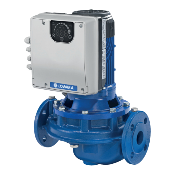
- Page 1 Smart Pump Range Installation, Operation and Maintenance Manual LNTSE LNEEE LNESE LNTEE Cod.001080138EN rev.A ed.04/2017 Software Version 151.00...
-
Page 2: Table Of Contents
en – Original instructions Table of Contents Introduction and safety .............................5 Introduction ................................5 1.1.1 Qualified personnel ............................5 Safety .................................5 1.2.1 Safety message levels ...........................6 User safety .................................7 Inexperienced users ............................8 Protecting the environment..........................8 Warranty ................................9 Spare parts ................................9 DECLARATION OF CONFORMITY ........................9 1.8.1 EC Declaration of Conformity (Original) ......................9 1.8.2... - Page 3 en – Original instructions Electrical requirements ..........................23 Wire type and ratings ............................ 24 Power supply connection ..........................24 Operation ................................27 Discharge time ............................... 27 Programming ................................28 Control panel ..............................28 Functions of push buttons ..........................29 LEDs description ............................29 7.3.1 Power LED (2) ............................
-
Page 5: Introduction And Safety
This includes any modification to the equipment or use of parts not provided by Xylem. If there is a question regarding the intended use of the equipment, please contact a Xylem representative before proceeding. -
Page 6: Safety Message Levels
en – Original instructions 1.2.1 Safety message levels About safety messages It is extremely important that you read, understand, and follow the safety messages and regulations carefully before handling the product. They are published to help prevent these hazards: • Personal accidents and health problems •... -
Page 7: User Safety
en – Original instructions Specific information for users of the product. 1.3 User safety General safety rules These safety rules apply: • Always keep the work area clean. • Pay attention to the risks presented by gas and vapors in the work area. •... -
Page 8: Inexperienced Users
• Clean-up of spills. Exceptional sites CAUTION: Radiation Hazard Do NOT send the product to Xylem if it has been exposed to nuclear radiation, unless Xylem has been informed and appropriate actions have been agreed upon. Recycling guidelines Always follow local laws and regulations regarding recycling. -
Page 9: Warranty
1.8 DECLARATION OF CONFORMITY 1.8.1 EC Declaration of Conformity (Original) Xylem Service Italia S.r.l., with headquarters in Via Vittorio Lombardi 14 - 36075 Montecchio Maggiore VI - Italy, hereby declares that the product: In-line electric pump unit with integrated variable speed drive, with or without pressure... - Page 10 – Original instructions Signed for and on behalf of: Xylem Service Italia S.r.l. Montecchio Maggiore, 22/03/2017 Amedeo Valente (Director of Engineering and R&D) rev.01 Lowara is a trademark of Xylem Inc. or one of its subsidiaries.
-
Page 11: Storage And Transportation
en – Original instructions 2 Storage and Transportation 2.1 Inspect the package 1. Inspect the package for damaged or missing items upon delivery. 2. Note any damaged or missing items on the receipt and freight bill. 3. File a claim with the shipping company if anything is out of order. 4. -
Page 12: Lifting Diagrams
en – Original instructions WARNING: Crush Hazard 1. Always lift the unit by its designated lifting points. 2. Use suitable lifting equipment and ensure that the product is properly harnessed. 3. Wear personal protective equipment. 4. Stay clear of cables and suspended loads. 2.5.1 Lifting diagrams Figure 1: Lifting... -
Page 13: Product Description
en – Original instructions 3 Product Description 3.1 Product design The product is a single stage in-line pump with: • The water inlet on the same axis as the water outlet of the pump • The suction and discharge nozzles with the same nominal diameter of the flange. The pump is equipped with a single radial closed impeller and driven by a variable speed electric motor. -
Page 14: Applications
en – Original instructions • If the density and/or viscosity value of the pumped liquid exceeds the value of water, such as water with glycol; as it may require a more powerful motor. • If the pumped liquid is chemically treated (for example softened, deionized, demineralized etc.). -
Page 15: Pump
en – Original instructions Motor type definition code Figure 3: Motor type definition code 1. Series 2. Motor frame 90R: Oversized Flange dimension 80: Standard Flange 3. Shaft extension □□: Standard sha extension S8: Custom Shaft extension 4. Power supply 1: single phase power supply 3: three phase power supply 5. - Page 16 en – Original instructions 1. Electropump unit type 11. Head range 2. Serial number (date+progressive number) 12. Motor nominal power 3. Capacity range 13. Maximum operating liquid temperature 4. Minimum head (EN 60335-2-41) 14. Protection class 5. Maximum operating pressure 15.
-
Page 17: Motor Technical Data
en – Original instructions 3.4 Motor technical data Table 1: Electrical, Environmetal and Installation specifications e-SM Drive model Input Input frequency [Hz] 50/60 ± 2 Mains supply L1 L2 L3 380÷ Nominal input voltage [V] 208÷240 ±10% 208÷240 / 380÷460 ±10% ±10% Max. - Page 18 en – Original instructions Figure 6: Dimensions Table 2: Dimensions and weights Net weight (motor + drive) D1 D2 D3 [kg] Model 30 (900W) 60 (1700W) [mm] 90R...LNEE 90RS8..LNEE 90R...B14-SVE 90R...B5 80...HMHA 80...HMHA US 100 125 80...HMHA EU 80...HMHB 80...HMHB US 100 125 80...HMHB EU 80...HMVB...
-
Page 19: Design And Layout
en – Original instructions 3.6 Design and layout Parts and descriptions The unit can be fitted with the features the application requires. Figure 7: Open terminal box cover on drive models 103, 105, 107, 111, 115 Table 4: Part description Position Description Tightening torque... -
Page 20: Pre-Assembled Ex Factory Components
en – Original instructions 3.7 Pre-assembled ex factory components Table 5: Included components Included components Cable Outer Diameter e-SM Drive model [mm (in)] 103, 105, 107, 303, 305, 307, 111, 115 311, 315, 322 Cable Gland(s) and Lock 3.7÷7.0 (0.145÷0.275) Nut(s) 4.5÷10.0 (0.177÷0.394) Cable Gland... -
Page 21: Mechanical Installation
en – Original instructions 4 Mechanical Installation 4.1 Installation site checklist DANGER: Never install the unit in an explosive or flammable environment. WARNING: • Always refer to the local and national regulations, legislation, and codes in force regarding selection of installation site, and water and power connections. •... -
Page 22: Outdoor Installation
en – Original instructions 4.3 Outdoor installation When the unit is installed outdoors a suitable cover must be provided. See Figure 9. Figure 9: Outdoor installation The cover must be sized to ensure that the motor is not exposed to snow, rain or direct sunlight. When fitting a cover to the motor, observe the guideline in section 3.6, table 4. -
Page 23: Electrical Installation
en – Original instructions 5 Electrical Installation 5.1 Precautions WARNING: EQUIPMENT HAZARD. Rotating shafts and electrical equipment can be hazardous. All electrical work must conform to national and local electrical codes. Installation, start-up, and maintenance must be performed by trained and qualified personnel. Failure to follow these guidelines could result in death or serious injury. -
Page 24: Wire Type And Ratings
en – Original instructions • Proper protective grounding for equipment with ground currents higher the 3.5 mA must be established. See the Leakage current (>3.5 mA) section for details. • Keep the ground wire connections as short as possible. • Use high-strand wire to reduce electrical noise is recommended. 5.3 Wire type and ratings •... - Page 25 en – Original instructions Table 9: Power supply wiring procedure Reference Figure e-SM Drive models e-SM Drive models 103, 105, 107, 111, 303, 305, 307, 311, 315, 322 1. Open the terminal box cover, remove the screws (1). Fig. 7 2.
- Page 26 en – Original instructions Table 10: I/O wiring procedure Reference Figure e-SM Drive models e-SM Drive models 103, 105, 107, 111, 303, 305, 307, 311, 315, 322 1. Open the terminal box cover, remove the screws (1) Fig. 7 2. Use M16 and M12 cable glands for I/O cables. 3.
-
Page 27: Operation
en – Original instructions 6 Operation In case of co-existance of two or more of the following conditions: • high ambient temperature • high liquid temperature • duty points insisting on unit maximum power • persisting undervoltage of mains, life expectancy of the unit may be affected and/or derating may occur: contact our Sales and Service Department for more information. -
Page 28: Programming
en – Original instructions 7 Programming Precautions NOTICE: Read and follow the operating instructions carefully before you start programming. This is to prevent incorrect settings which cause malfunction. All modifications must be done by qualified technicians. 7.1 Control panel Figure 12: Control panel Table 13: Part description Position Description... -
Page 29: Functions Of Push Buttons
en – Original instructions 7.2 Functions of push buttons Table 14: Functions of push buttons Push button Function 1. Main Visualization (see par. 7.4.1): decrease the required value related to the selected control mode. 2. Parameters Menu Visualization (see par. 7.4.2): decrease the parameter index visualized. -
Page 30: Communication Led (1)
en – Original instructions LEDs are lit if motor is running and its speed reaches the specific % step represented by each of them. If motor is running and its speed is lower than the absolute minimum (P27), the first LED blinks. When motor is stopped, all arc’s LEDs are switched off. -
Page 31: Parameters Menu Visualization
en – Original instructions Off mode, has lower visualization priority than Stop mode. Stop mode is visualized when the pump is manually stopped. To manually stop the pump, follow next examples: • Example 1 (valid for CPP, PPP control modes with an initial required value (Head) of 4.20 bar and a minimum value of 0.5 bar): 4. -
Page 32: Alarms And Errors Visualization
en – Original instructions → → → Parameter’s index blinks to indicate the possibility of parameter selection. Parameters Editing/Visualization Accessing to a parameter’s value, if the parameter is both readable and writable, its value can be changed using the push buttons or trough communication protocol (Modbus or BACnet). Going back to Parameters Menu, the index of visualized parameter is automatically increased. - Page 33 en – Original instructions VALUE: can represent a Speed or a Head, dependent from selected control mode. In case of Head, the unit of measure is defined by parameter P41. P05. Operating time months It shows the amount of months of total operating time (drive supplied with power), to be added to P06.
-
Page 34: Settings Parameters
en – Original instructions P16. Motor Speed It shows the actual motor rotational speed, expressed in revolutions for minute. P17. Software version It shows the Control Board software version. 7.5.2 Settings Parameters P20. Password [0÷999] The user can enter here the system password, which gives access to all system parameters: this value is compared with the one stored in P22. -
Page 35: Sensor Configuration Parameters
en – Original instructions P26. Max rpm set [ACT set÷Max] It sets the maximum speed of the pump, expressed in rpmx10. Maximum speed is model dependant. P27. Min rpm set [Min÷ACT set] It sets the minimum speed of the pump, expressed in rpmx10. Minimum speed is model dependant. -
Page 36: Test Run Configuration Parameters
en – Original instructions P51. BMS Comm Protocol – Address 1÷247 / 0÷127 This parameter sets the desired address for the drive, when connected to any external device, depending on the protocol selected in P50: • If P50 = MOd, the address can be any value in the range 1÷247 •... -
Page 37: Alarm Codes
en – Original instructions 7.6.1 Alarm codes Table 15: Alarm codes Alarm Description Cause code Derating Temperature too high Data memory alarm Data memory corrupted LOW alarm Lack of water detection (if P48= ALR) EEPROM write failure Internal alarm 7.6.2 Error codes Table 16: Error codes Error Description... -
Page 38: Maintenance
en – Original instructions 8 Maintenance 8.1 General Electrical Hazard: Before any service or maintenance disconnect the system from the power supply and wait at least 4 minutes before starting work on or in the unit (the capacitors in the intermediate circuit are discharged by the internal discharge resistors). -
Page 39: Technical Reference
en – Original instructions 9 Technical Reference 9.1 Example: ACT control mode with analog 0-10V input Graph Figure 13: ACT control mode diagram Table 17: Description → Missing input Voltage detection threshold Gray area → Actual Speed related to analog 0-10V input Voltage value (see par. 5.4, contacts 7 and 8) Speed [rpm] →... - Page 40 en – Original instructions...
- Page 41 Xylem Service Italia S.r.l. Via Vittorio Lombardi 14 36075 – Montecchio Maggiore (VI) - Italy www.xyleminc.com/brands/lowara Lowara is a trademark of Xylem Inc. or one of its subsidiaries. © 2017 Xylem, Inc.
Need help?
Do you have a question about the LOWARA LNTSE and is the answer not in the manual?
Questions and answers