
Related Manuals for EWM PM 221 G


Summary of Contents for EWM PM 221 G
- Page 1 Operating instructions welding torch PM 221 G PM 301 G PM 401 G 099-700000-EW501 Observe additional system documents! 22.09.2020...
- Page 2 +49 2680 181-0. A list of authorised sales partners can be found at www.ewm-group.com/en/specialist-dealers. Liability relating to the operation of this equipment is restricted solely to the function of the equipment. No other form of liability, regardless of type, shall be accepted.
-
Page 3: Table Of Contents
Contents Notes on using these operating instructions Contents 1 Contents ............................3 2 For your safety ..........................5 Notes on using these operating instructions ................5 Explanation of icons ....................... 6 Part of the complete documentation ..................7 3 Intended use ........................... 8 Applications .......................... - Page 4 Contents Notes on using these operating instructions 10 Replaceable parts ......................... 39 10.1 PM 221 G ..........................39 10.2 PM 301 G ..........................40 10.3 PM 401 G ..........................42 11 Service documents........................44 11.1 Circuit diagrams ........................44 11.1.1 PM 301 - 551 W ....................
-
Page 5: For Your Safety
For your safety Notes on using these operating instructions For your safety Notes on using these operating instructions DANGER Working or operating procedures which must be closely observed to prevent imminent serious and even fatal injuries. • Safety notes include the "DANGER" keyword in the heading with a general warning symbol. •... -
Page 6: Explanation Of Icons
For your safety Explanation of icons Explanation of icons Symbol Description Symbol Description Indicates technical aspects which the u- Activate and release / Tap / Tip ser must observe. Switch off machine Release Switch on machine Press and hold Switch Incorrect / Invalid Turn Correct / Valid... -
Page 7: Part Of The Complete Documentation
For your safety Part of the complete documentation Part of the complete documentation This document is part of the complete documentation and valid only in combination with all other parts of these instructions! Read and observe the operating instructions for all system components, especially the safety instructions! The illustration shows a general example of a welding system. -
Page 8: Intended Use
3.2.1 Warranty For more information refer to the "Warranty registration" brochure supplied and our information regarding warranty, maintenance and testing at www.ewm-group.com! 3.2.2 Declaration of Conformity This product corresponds in its design and construction to the EU directives listed in the decla- ration. -
Page 9: Product Description - Quick Reference
Product description – quick reference Product variants Product description – quick reference Product variants Version Functions Performance class Professional MIG PM221/301/401G, PM301/451/551W Water-cooled PM301/451/551W You use the torch trigger to switch the welding process on and off. Interchangeable contact tip holder. Gas-cooled PM221/301/401G You use the torch trigger to switch the welding process on and... -
Page 10: Standard Welding Torch
Product description – quick reference Standard welding torch Standard welding torch Figure 4-1 Item Symbol Description Gas nozzle Grip plate Ball joint Anti-kink device Lock ring Torch trigger Torch neck 45° 099-700000-EW501 22.09.2020... -
Page 11: Function Torch
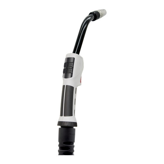
Product description – quick reference Function torch Function torch Figure 4-2 Item Symbol Description Gas nozzle Torch neck 45° Operating elements Grip plate Ball joint Anti-kink device Lock ring Torch trigger LED lighting Euro torch connector without control cable Figure 4-3 Item Symbol Description Anti-kink spring... -
Page 12: Euro Torch Connector With Control Cable
Product description – quick reference Euro torch connector with control cable Euro torch connector with control cable Figure 4-4 Item Symbol Description Anti-kink spring Euro central connection Control cable plug Only for control variant 2U/D. Version with control cable only with control variant 2U/D. 099-700000-EW501 22.09.2020... -
Page 13: Design And Function
Design and function Transport and installation Design and function WARNING Risk of injury from electrical voltage! Contact with live parts, e.g. power connections, can be fatal! • Observe the safety information on the first pages of the operating instructions! • Commissioning must be carried out by persons who are specifically trained in handling power sources! •... -
Page 14: Transport And Storage
The full functional range of the PM function torch is only available in connection with the device series Titan XQ and the wire feeder drive XQ. If the function torch is connected to another EWM device series using Multimatrix, the welding torch swit- ches to compatibility mode and is restricted in its functions. -
Page 15: Operating Elements 2 For Up/Down Welding Torch
Design and function Transport and installation 5.1.4 Operating elements 2 for up/down welding torch Figure 5-2 Item Symbol Description "B -" button (program mode) Decrease JOB number "B -" button (up/down mode) Welding voltage correction, decrease value "B +" button (program mode) Increase JOB number "B +"... -
Page 16: Welding Data Display
Design and function Transport and installation Item Symbol Description "B +" button (program mode) Increase JOB number "B +" button (up/down mode) Welding voltage correction, increase value "A -" button (Program mode) Decrease program number "A -" button (Up/Down mode) Reduce welding performance (welding current/wire-feed speed) "A +"... -
Page 17: Operating Elements For Rd3 Welding Torch
Design and function Transport and installation 5.1.7 Operating elements for RD3 welding torch Figure 5-4 Item Symbol Description OLED display Graphical display to show the functions. Parameter selection push-button Welding parameters are selected one after the other. Parameter selection push-button Welding parameters are selected one after the other. -
Page 18: Welding Data Display
Design and function Transport and installation 5.1.8 Welding data display The display shows the currently selected welding parameter and the corresponding parameter value. When the welding machine is switched on, the display shows the nominal welding current set point set point set by the control unit. -
Page 19: Programs, Setting Operating Points
Design and function Transport and installation 5.1.8.1 Programs, setting operating points Distinction is made between main and program level during the parameter setting. After switching on the welding machine, you are always at the main level. Process switching, program number, wire feed speed, dynamics (hard to soft arc), welding current and welding voltage are specified here. - Page 20 Design and function Transport and installation Program level Figure 5-6 099-700000-EW501 22.09.2020...
-
Page 21: Component Management On The Welding Torch
Design and function Transport and installation 5.1.8.2 Component management on the welding torch The Xnet component management software can be used to manage components, create welding se- quence plans and assign WPS. The display shows seams and runs. After completion they can be ack- nowledged with the burner. -
Page 22: Led Lighting
Design and function Configure welding torch 5.1.9 LED lighting Integrated LED lighting makes welding in corners and dark areas of the working area easier. The lighting switches on independently of the burner button when the burner is moved. After approx. 10 seconds wit- hout movement, the light switches off automatically. -
Page 23: Turning The Torch Neck
Design and function Configure welding torch Equipment damage and impurities of the welding result due to worn O-rings. Worn O-rings have a negative impact on the torch cooling. Insufficient cooling causes damage to the welding torch. Gas losses and the penetration of atmospheric oxygen can also occur and can adversely affect the welding result. - Page 24 Design and function Configure welding torch Figure 5-11 Item Symbol Description Grip plate Crown nut Torch neck 45° Gas nozzle Contact tip holder Liner Contact tip Connect welding torch after performing the maintenance and rinse using the "Gas Test" with shield gas.
-
Page 25: Equipment Recommendations
Design and function Equipment recommendations Equipment recommendations Figure 5-12 099-700000-EW501 22.09.2020... -
Page 26: Adapting The Euro Torch Connection On The Device
• Refer to the manufacturer instructions for the right wire feed unit equipment. Refer to Annex 1 in these operating instructions for the right EWM machine equipment. • Use a steel liner inside the torch hose package to guide hard, unalloyed wire electrodes (steel)! •... -
Page 27: Liner
Design and function Assemble the wire guide 5.5.1 Liner Observe permissible torque! The distance between the plastic liner and drive rollers should be as short as possible. Use only sharp, stable knives or special tongs for cutting to ensure that the plastic liner does not become misshapen! Always make sure the the hose package is straight when replacing the wire guide. - Page 28 Design and function Assemble the wire guide Figure 5-16 Adjust the brass liner . Figure 5-17 Figure 5-18 Figure 5-19 099-700000-EW501 22.09.2020...
- Page 29 Design and function Assemble the wire guide Figure 5-20 Figure 5-21 Item Symbol Description Gas nozzle Contact tip Contact tip holder Torch neck 45° Crown nut O-ring Collet Combined liner Euro central connection Connecting sleeve New combined liner Liner sharpener Guiding tube for welding torch Euro torch connector 099-700000-EW501 22.09.2020...
-
Page 30: Guide Spiral
Design and function Assemble the wire guide 5.5.2 Guide spiral Observe permissible torque! Insert the grinded end towards the contact tip holder to ensure tight fit with the contact tip. Always make sure the the hose package is straight when replacing the wire guide. Figure 5-22 Figure 5-23 Figure 5-24... - Page 31 Design and function Assemble the wire guide Figure 5-25 Figure 5-26 Figure 5-27 099-700000-EW501 22.09.2020...
- Page 32 Design and function Assemble the wire guide Figure 5-28 Figure 5-29 Item Symbol Description Gas nozzle Contact tip Contact tip holder Welding torch neck Crown nut Centring sleeve old spiral guide Euro central connection new spiral guide Capillary tube 099-700000-EW501 22.09.2020...
-
Page 33: Maintenance, Care And Disposal
Maintenance, care and disposal General Maintenance, care and disposal General DANGER Risk of injury due to electrical voltage after switching off! Working on an open machine can lead to fatal injuries! Capacitors are loaded with electrical voltage during operation. Voltage remains present for up to four minutes after the mains plug is removed. -
Page 34: Maintenance Work, Intervals
Maintenance, care and disposal Maintenance work, intervals Maintenance work, intervals 6.2.1 Daily maintenance tasks Figure 6-1 • Purge the wire guide from the direction of the Euro torch connector with oil- and condensate-free com- pressed air or shielding gas. • Check that coolant connections are tight. -
Page 35: Disposing Of Equipment
• Information about returning used equipment or about collections can be obtained from the respective municipal administration office. • In addition to this, returns are also possible throughout Europe via EWM sales partners. 099-700000-EW501 22.09.2020... -
Page 36: Rectifying Faults
Rectifying faults Checklist for rectifying faults Rectifying faults All products are subject to rigorous production checks and final checks. If, despite this, something fails to work at any time, please check the product using the following flowchart. If none of the fault rectification procedures described leads to the correct functioning of the product, please inform your authorised dea- ler. -
Page 37: Technical Data
Technical data PM 221-, 301-, 401 G Technical data PM 221-, 301-, 401 G Performance specifications and guarantee only in connection with original spare and replacement parts! - 221 G - 301 G - 401 G Welding torch polarity Usually positive Guide type Manually operated Voltage type... -
Page 38: Accessories
Accessories General accessories Accessories General accessories Type Designation Item no. ON TT PM Standard Conversion kit, upper torch trigger, for PM standard 092-007938-00000 welding torch ON HSS 18-10 mm Heat shield for PM/MT welding torch 094-025359-00000 ON TH PM Optional pistol grip 092-007944-00000 ON TV PM LED... -
Page 39: Replaceable Parts
Replaceable parts PM 221 G Replaceable parts Parts and / or wearing parts may only be replaced when the components have cooled down and switched off! 10.1 PM 221 G Figure 10-1 Item Order number Type Name 094-013061-00001 GN TR 20 66mm D=13mm... -
Page 40: Pm 301 G
Replaceable parts PM 301 G Item Order number Type Name 094-020690-00000 CT M6 x 25 mm, 1.0 mm, CuCrZr Contact tip 094-020691-00000 CT M6 x 25 mm, 0.6 mm, E-Cu Contact tip 094-020692-00000 CT M6 x 25 mm, 0.8 mm, E-Cu Contact tip 094-020693-00000 CT M6 x 25 mm, 0.9 mm, E-Cu Contact tip... - Page 41 Replaceable parts PM 301 G Item Order number Type Name 094-019554-00000 GN FCW TR 22x4 59.5MM Gas nozzle, Inner shield 094-019626-00000 GN NG M12 73mm Gas nozzle, Narrow gap welding 094-022226-00000 GN NG M12 76mm Gas nozzle, Narrow gap welding 094-019623-00000 GNC TR22x4 Gas nozzle body 094-020945-00000 GN TR 22, 80 mm, D=20 mm...
-
Page 42: Pm 401 G
Replaceable parts PM 401 G Item Order number Type Name 094-013540-00002 CTH M9 CuCrZr 37.5mm Contact tip holder 094-013096-00004 GD Ø11,7 mm, L=14 mm Gas diffuser 094-019625-00000 IT ES M22X1,5 M12X1 Insulation part 094-019627-00000 ZH GDE ID=5MM AD=10MM L=15MM Centring sleeve 094-016038-00001 TT SW5-SW12MM Torch key 094-013967-00000 4,0MMX1,0MM... - Page 43 Replaceable parts PM 401 G Item Order number Type Name 094-013548-00001 CTAL E-CU M9X35MM D=1.6MM Contact tip, Aluminium welding 094-013549-00001 CTAL E-CU M9X35MM D=2.0MM Contact tip, Aluminium welding 094-014024-00000 CT CUCRZR M8X30MM D=0.8MM Contact tip 094-014191-00000 CT CUCRZR M8X30MM D=1.4MM Contact tip 094-014192-00000 CT CUCRZR M8X30MM D=1.6MM Contact tip...
-
Page 44: Service Documents
Service documents Circuit diagrams Service documents 11.1 Circuit diagrams The circuit diagrams are only intended for authorised service personnel! 11.1.1 PM 301 - 551 W Figure 11-1 099-700000-EW501 22.09.2020... -
Page 45: 11.1.2 Pm 301 - 551 W Led
Service documents Circuit diagrams 11.1.2 PM 301 - 551 W LED Figure 11-2 099-700000-EW501 22.09.2020... -
Page 46: 11.1.3 Pm 301 - 551 W Tt
Service documents Circuit diagrams 11.1.3 PM 301 - 551 W TT Figure 11-3 099-700000-EW501 22.09.2020... -
Page 47: 11.1.4 Pm 301 - 551 W Tt Led
Service documents Circuit diagrams 11.1.4 PM 301 - 551 W TT LED Figure 11-4 099-700000-EW501 22.09.2020... -
Page 48: 11.1.5 Pm 301 - 551 W 2U/D
Service documents Circuit diagrams 11.1.5 PM 301 - 551 W 2U/D Figure 11-5 099-700000-EW501 22.09.2020... -
Page 49: 11.1.6 Pm 301 - 551 W 2U/Dx
Service documents Circuit diagrams 11.1.6 PM 301 - 551 W 2U/DX Figure 11-6 099-700000-EW501 22.09.2020... -
Page 50: Pm 301 - 551 W Rd2 X
Service documents Circuit diagrams 11.1.7 PM 301 - 551 W RD2 X Figure 11-7 099-700000-EW501 22.09.2020... -
Page 51: Pm 301 - 551 W Rd3 X
Service documents Circuit diagrams 11.1.8 PM 301 - 551 W RD3 X Figure 11-8 099-700000-EW501 22.09.2020... -
Page 52: Appendix
Appendix Display, explanation of symbols Appendix 12.1 Display, explanation of symbols Main level Display Setting/selection Welding current Welding voltage Welding voltage correction Dynamics Wire feed speed Unit: m/min Wire feed speed Unit: ipm Program selection Welding procedure MIG/MAG Welding procedure forceArc Welding procedure wiredArc... - Page 53 Appendix Display, explanation of symbols Error messages, warnings Display Setting/selection Error Error - temperature Error - water Warning Warning wire end Component management, Miscellaneous Display Setting/selection Unit completed Scan component Free-welding mode Hold value Correction mode Seam run Seam end End of component End of component, confirmation WPS End...
-
Page 54: Searching For A Dealer
Appendix Searching for a dealer 12.2 Searching for a dealer Sales & service partners www.ewm-group.com/en/specialist-dealers "More than 400 EWM sales partners worldwide" 099-700000-EW501 22.09.2020...
Need help?
Do you have a question about the PM 221 G and is the answer not in the manual?
Questions and answers