Table of Contents
Advertisement
Quick Links
Advertisement
Table of Contents

Summary of Contents for Panametrics BWT System
- Page 1 Flow BWT™ System Installation Guide 916-058 F panametrics.com July 2021...
- Page 3 Installation Guide 916-058 F July 2021 panametrics.com Copyright 2021 Baker Hughes company. This material contains one or more registered trademarks of Baker Hughes Company and its subsidiaries in one or more countries. All third-party product and company names are trademarks of their respective...
- Page 4 [no content intended for this page]...
- Page 5 Chapter Information Paragraphs Note: These paragraphs provide information that provides a deeper understanding of the situation, but is not essential to the proper completion of the instructions. IMPORTANT: These paragraphs provide information that emphasizes instructions that are essential to proper setup of the equipment.
- Page 6 Chapter Qualification of Personnel Make sure that all personnel have manufacturer-approved training applicable to the auxiliary equipment. Personal Safety Equipment Make sure that operators and maintenance personnel have all safety equipment applicable to the auxiliary equipment. Examples include safety glasses, protective headgear, safety shoes, etc. Unauthorized Operation Make sure that unauthorized personnel cannot gain access to the operation of the equipment.
-
Page 7: Table Of Contents
Contents Chapter 1. General Information Introduction ..................... .1 Types of BWT Buffers. - Page 8 Contents BWT™ System Installation Guide...
-
Page 9: Chapter 1. General Information
System consists of creating a meter body, installing the transducer buffer, and then mounting transducers into the buffer. Panametrics offers a variety of buffers and meter bodies for liquid and gas applications. This section consists of general information for the following topics: •... -
Page 10: General Guidelines For Transducer Position And Location
Chapter 1. General Information • Non-Flanged BWT Buffer (part number FSPA) - is used in liquid applications and has a 1 in. NPT thread. • Socket-Weld BWT Buffer (part number FWPA) - is used in liquid applications and has a 1 in. coupling that is welded into the pipe coupling. General Guidelines for Transducer Position and Location WARNING! For installations in potentially hazardous areas, be sure to read the Certification and... -
Page 11: Bwt Meter Body
Chapter 1. General Information BWT Meter Body BWT installations typically use a tilted-diameter meter body. A tilted-diameter meter body is so named because the transducers send their pulses at an angle across the diameter of the pipe. This type of meter body can be configured as a single-traverse or double-traverse installation. -
Page 12: Double-Traverse Meter Body
Chapter 1. General Information 1.4.2 Double-Traverse Meter Body A double-traverse configuration consists of two transducers mounted on the pipe so that the signal traverses the fluid two times before reaching the other transducer (see Figure 3 below). P = Distance that the signal travels through the liquid from one transducer to the other. -
Page 13: Handling And Installing A Meter Body
Chapter 1. General Information Handling and Installing a Meter Body To ensure proper nozzle alignment, Panametrics uses the highest quality welding and machining techniques when manufacturing meter bodies. Since proper alignment of the nozzles is important to making accurate flow measurement, great care must be taken when unpacking and installing the meter body. - Page 14 Chapter 1. General Information Bolt holes straddle the centerline symmetrically Top View End View Figure 4: Top View of a Flanged Meter Body BWT™ System Installation Guide...
-
Page 15: Welding Requirements
Meter Body Requirements When Flushing Panametrics strongly recommends using a dummy meter body during flushing operations; otherwise, damage may occur for the following reasons: • Fast moving solid objects in the flowing medium could damage the buffer faces. - Page 16 Chapter 1. General Information [no content intended for this page] BWT™ System Installation Guide...
-
Page 17: Chapter 2. Standard Installation (Ftpa Buffers)
Panametrics cannot ensure the proper operation of your equipment. Panametrics supplies the parts required for your intended installation. Before you install the FTPA Buffer, check the lists below to make sure you have all of the needed components. Refer to Figure 5 on page 10 and Figure 6 on page 10 to help you identify each component. - Page 18 Chapter 2. Standard Installation (FTPA Buffers) FTPA Buffer BWT Transducer Junction Box Mating Lap-Joint Flange Figure 5: Components for FTPA Buffer Kamprofile with Metal Centering Ring (Typical) Kamprofile without Ring Metal Centering Figure 6: Gaskets BWT™ System Installation Guide...
-
Page 19: Assembling The Standard Ftpa Buffer
Assembling the Standard FTPA Buffer Note: If the BWT system is shipped with the buffers already installed in the nozzles, proceed to “Installing the BWT Transducer” on page 16 . Slide the lap-joint flange over the threaded end of the FTPA Buffer. Make sure you orient the flange as shown below. -
Page 20: Inserting The Standard Ftpa Buffer
Chapter 2. Standard Installation (FTPA Buffers) Inserting the Standard FTPA Buffer Inspect the pipe nozzle. Make sure it is free from dirt and rust. Use steel wool to clean the pipe nozzle face and inside surfaces if necessary. Insert the buffer assembly into the nozzle. Nozzle Side View Side View... - Page 21 Chapter 2. Standard Installation (FTPA Buffers) Side View Equal Amount of Threads Stud Quality Rating Side View Install the remaining studs in the order shown below, but do not fully tighten the nuts yet. 8-Hole Flange 4-Hole Flange Center the buffer in the middle of the lap joint flange. Inspect 360° around the flanges to ensure equal spacing, by sliding your fingers around the gap between the buffer flange and the nozzle flange.
- Page 22 Chapter 2. Standard Installation (FTPA Buffers) Flange Proper Gasket Alignment End View Good Tighten the nuts on the studs further by hand to maintain the centering. Visually verify that the buffer is centered in the lap joint flange. If necessary, adjust the buffer by hand until it is centered. It is important to torque the studs properly for a good seal.
- Page 23 Chapter 2. Standard Installation (FTPA Buffers) Turn first nut 1/8 turn. 8-Hole Flange 4-Hole Flange Turn the nut on the second stud 1/8 turn. The second stud should be diametrically opposite the first stud. Proceed to tighten the remaining studs in the order shown below, or in a similar manner. Turn second nut 1/8 turn.
-
Page 24: Installing The Bwt Transducer
Chapter 2. Standard Installation (FTPA Buffers) Table 1: Final Torques Flange Size Stud Rating with Stud Diameter (in.) Torque in and Rating 4 Studs/Flange x Length (in.) ft-lb (N-m) 1 1/2" ANSI 900# 1" x 6 " 107 (145) 1 1/2" ANSI 1500# 1"... -
Page 25: Installing And Orienting The Junction Box
Chapter 2. Standard Installation (FTPA Buffers) 2.5.1 Installing and Orienting the Junction Box Before placing the BWT transducer into the FTPA buffer permanently, you must make sure the junction box will be properly oriented after it is installed. Screw the transducer into the junction box as shown below. Screw the transducer/junction box assembly into the FTPA Buffer. -
Page 26: Inserting The Bwt Transducer
Chapter 2. Standard Installation (FTPA Buffers) 2.5.2 Inserting the BWT Transducer Please read the following steps completely before beginning the installation of the BWT transducer. IMPORTANT: After you install the BWT transducers, you must allow the epoxy to cure for eight hours. Note: In gas applications, the typical minimum pressure should be 5 barg (75 psig) for the transducers to receive any signal. -
Page 27: Verifying The Installation
Chapter 2. Standard Installation (FTPA Buffers) CAUTION! Do not place insulation on or around the transducer or junction box. The transducer and junction box act as a heat sink that protects the transducer from high and low temperatures. After you install the FTPA Buffers and transducers, you must allow the epoxy to cure for eight hours. However, while the epoxy cures, you should verify that the transducer and buffer are working properly (see the next section). - Page 28 Chapter 2. Standard Installation (FTPA Buffers) [no content intended for this page] BWT™ System Installation Guide...
-
Page 29: Chapter 3. Acoustic Isolation Installation (Fipa Buffers)
Panametrics cannot ensure the proper operation of your equipment. Panametrics supplies the parts required for your installation. Before you begin, check the lists below to make sure you have all of the needed components. Refer to Figure 7 on page 22 and Figure 8 on page 22 to help you identify each component. - Page 30 Chapter 3. Acoustic Isolation Installation (FIPA Buffers) Acoustic Isolation FIPA Buffer - fully assembled BWT Transducer Junction Box Figure 7: Components for Acoustic Isolation FIPA Buffer Kamprofile with Metal Centering Ring (Typical) Kamprofile without Metal Centering Ring Figure 8: Gaskets BWT™...
-
Page 31: Inserting The Acoustic Isolation Fipa Buffer
Note: If the BWT system is shipped with the buffers already installed in the nozzles, proceed to “Installing the BWT Transducer” on page 30 . Check the raised face of the spool nozzle flange to make sure it is free from paint, rust, dirt, corrosion, and damage. - Page 32 Chapter 3. Acoustic Isolation Installation (FIPA Buffers) Inspect Pipe Nozzle Top View Insert the buffer/gasket assembly into the nozzle. Gasket Nozzle Top View Buffer Gasket Nozzle Top View Apply Copperslip, Molykote or equivalent anti-seize compound on the first several threads at both ends of each stud.
- Page 33 Chapter 3. Acoustic Isolation Installation (FIPA Buffers) CAUTION! Do not adjust the studs on the FIPA isolation flange. The isolation flange is already set to specification determined at the factory. Isolation Flange Top View Stud Quality Rating Equal Amount of Threads Top View Install the remaining studs in the order shown below, but do not fully tighten the nuts yet.
- Page 34 Chapter 3. Acoustic Isolation Installation (FIPA Buffers) Inspect 360° around the flanges to ensure equal spacing, by sliding your fingers around the gap between the buffer flange and the nozzle flange. 10. Then align the flanges as shown below. IMPORTANT: Make sure the gasket is in the center of the flanges. Flange Proper Gasket Alignment...
-
Page 35: Torquing The Studs
Chapter 3. Acoustic Isolation Installation (FIPA Buffers) Torquing the Studs It is important to torque the studs properly for a good seal. However, do not over-torque them or you will cause an acoustic short or change the transducer alignment. Tighten and torque the studs in increments, as described below. Check the flange and buffer alignment again. - Page 36 Chapter 3. Acoustic Isolation Installation (FIPA Buffers) Turn first nut 1/8 turn. 8-Hole Flange 4-Hole Flange Turn the nut on the second stud 1/8 turn. The second stud should be diametrically opposite the first stud. Proceed to tighten the remaining studs in the order shown below, or in a similar manner. Turn second nut 1/8 turn.
- Page 37 Chapter 3. Acoustic Isolation Installation (FIPA Buffers) You must torque the flange studs in small increments. Divide the appropriate torque by 10 to determine the number of steps. For example, if the required final torque is 90 ft-lb, the remaining steps would be 20, 30, 40, 50, 60, 70, 80 and 90 ft-lb.
-
Page 38: Installing The Bwt Transducer
Chapter 3. Acoustic Isolation Installation (FIPA Buffers) Installing the BWT Transducer Installing the BWT transducers into the FIPA Buffer requires the following three steps: • Installing and orienting the junction box (see page 30 ) • Inserting the BWT transducers (see page 31 ) •... -
Page 39: Inserting The Bwt Transducer
Chapter 3. Acoustic Isolation Installation (FIPA Buffers) Good Remove the transducer/junction box assembly. Repeat the above steps for the other transducer. 3.5.2 Inserting the BWT Transducer Please read the following steps completely before beginning the installation of the BWT transducer. IMPORTANT: After you install the BWT transducers, you must allow the epoxy to cure for eight hours. - Page 40 Chapter 3. Acoustic Isolation Installation (FIPA Buffers) BWT Transducer/Junction Box Top View IMPORTANT: In the next step, DO NOT overtighten the transducer. Torque the transducer to a maximum of 15-18 ft-lb (20- 25 N-m). Verify that the junction box is properly oriented as discussed in the previous section (see page 30 ). To connect the transducer electrical cables, see the Startup or User’s Manual that was supplied with your flowmeter.
-
Page 41: Verifying The Installation
Chapter 3. Acoustic Isolation Installation (FIPA Buffers) 3.5.3 Verifying the Installation To verify that the installation is working properly, complete the following steps: Power up the electronics. Refer to Displaying Diagnostics in the flowmeter Service or User’s Manual to display the upstream and downstream transducer signal strength. - Page 42 Chapter 3. Acoustic Isolation Installation (FIPA Buffers) Loosen Using Allen Wrench Front View Place the collets on the buffer as shown below. 1 in. (25 mm) Ring Collets Top View Repeat the above steps for the other transducer. This completes the installation of the FIPA buffers and transducers. Refer to the flowmeter Startup Guide or User’s Manual for instructions on obtaining flow rate measurements.
-
Page 43: Chapter 4. Non-Flanged Installation (Fspa/Fwpa Buffers)
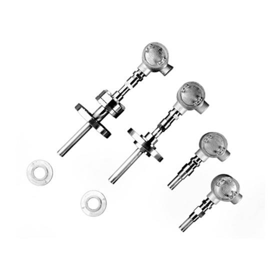
Chapter 4. Non-Flanged Installation (FSPA/FWPA Buffers) Chapter 4. Non-Flanged Installation (FSPA/FWPA Buffers) Introduction The non-flanged FSPA and FWPA buffers (see Figure 9 below) are available in either stainless steel or titanium. The FSPA is a threaded buffer that is screwed into the pipe coupling or nozzle, and the FWPA is a socket-weld buffer that is welded into the pipe coupling. -
Page 44: Installing The Fspa Or Fwpa Buffer
Chapter 4. Non-Flanged Installation (FSPA/FWPA Buffers) Installing the FSPA or FWPA Buffer Both types of buffers are easily installed into the pipe coupling or flange as follows: • FSPA Threaded Mount: Use Teflon tape thread sealant on the buffer threads and screw the buffer into the transducer port. -
Page 45: Installing And Orienting The Junction Box
Chapter 4. Non-Flanged Installation (FSPA/FWPA Buffers) Installing and Orienting the Junction Box Before placing the BWT transducer into the FSPA/FWPA buffer permanently, you must make sure the transducer junction box will be properly oriented after it is installed. Note: The figures below show the FSPA Buffer only as an example. Screw the transducer into the junction box as shown below. -
Page 46: Inserting The Bwt Transducers
Chapter 4. Non-Flanged Installation (FSPA/FWPA Buffers) Inserting the BWT Transducers WARNING! Follow all applicable safety codes and safety procedures when installing or removing the plugs. As shown below, place a small droplet (2 mm in diameter) of 3M Epoxy or equivalent on the center of the transducer face (the picture below shows the transducer without the junction box ). -
Page 47: Verifying The Installation
Chapter 4. Non-Flanged Installation (FSPA/FWPA Buffers) Verifying the Installation To verify that the installation is working properly, complete the following steps: Power up the electronics. Refer to Displaying Diagnostics in the flowmeter Service or User’s Manual to display the upstream and downstream transducer signal strength. - Page 48 Chapter 4. Non-Flanged Installation (FSPA/FWPA Buffers) [no content intended for this page] BWT™ System Installation Guide...
-
Page 49: Chapter 5. Specifications
• Minimum pressure (gas service): typically 100 psi (6.9 bar), depending on fluid density Note: Low-density, low-pressure gases use FIPA buffer assembly. No minimum pressure is required for liquid Area Classifications service. Consult Panametrics for individual application specifications. BWT™ System Installation Guide... -
Page 50: Threaded Buffer Assemblies
Chapter 5. Specifications Threaded Buffer Assemblies Service Liquids Mounting 1 in. NPT Materials • Standard: 316L stainless steel • Optional: Titanium Fluid Temperature • FSPA Short Buffers: -40°F to 212°F (-40°C to 100°C) • FSPA Extended Buffers: -40°F to 600°F (-40°C to 315°C) Socket-Weld Buffer Assemblies Service Liquids... - Page 51 Chapter 5. Specifications Note: For gas flow applications, a preamplifier is required. In such systems, the supplied preamplifiers may be mounted in the transducer junction boxes. BWT™ System Installation Guide...
- Page 52 Chapter 5. Specifications [no content intended for this page] BWT™ System Installation Guide...
- Page 53 • If Panametrics determines that the damage is not covered under the terms of the warranty, or if the warranty has expired, an estimate for the cost of the repairs at standard rates will be provided. Upon receipt of the owner’s approval to proceed, the instrument will be repaired and returned.
- Page 54 [no content intended for this page] BWT™ System Installation Guide...
- Page 55 The installation should comply with IEC / EN 60079-14. • The certification covers the Panametrics BWT transducer fitted with a Panametrics JB 6819 enclosure or with an ELFIT Sx-36 enclosure assembly. The enclosure assembly may contain a 705-1099 low power signal pre-amplifier.
- Page 56 National transposing legislation. BWT Transducer/Junction Box Details Manufacturer and certificate owner: Panametrics Sensing Inc, Billerica, MA 01821, USA. Alternative manufacturing site: Baker Hughes EMEA, Shannon, Co. Clare, Ireland QAN License Number:...
- Page 58 Customer Support Centers U.S.A. The Boston Center 1100 Technology Park Drive Billerica, MA 01821 U.S.A. Tel: 800 833 9438 (toll-free) 978 437 1000 E-mail: mstechsupport@bakerhughes.com Ireland Sensing House Shannon Free Zone East Shannon, County Clare Ireland Tel: +353 61 61470200 E-mail: mstechsupport@bakerhughes.com Copyright 2021 Baker Hughes company.
Need help?
Do you have a question about the BWT System and is the answer not in the manual?
Questions and answers