Advertisement
Quick Links
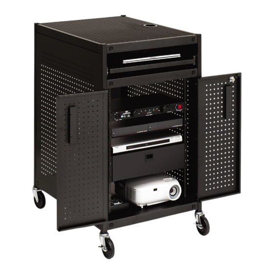
19" RACK PRESENTATION CART
WITH & WITHOUT POWER
Assembly Instructions
PARTS LIST
Qty
Part#
Description
2
022-2708
Leg Assembly Stamped with "X"
2
022-2709
Leg Assembly Stamped with "O"
1
022-2695
Top Shelf w/Grommet Hole
1
022-2699
Middle Shelf w/Grommet Hole
1
010-4791
Bottom Shelf
2
010-4785
Slide Bracket
2
030-1191
Slide
2
010-4780
Keyboard Shelf
1
010-4788
Front Panel
1
010-4789
Rear Panel
2
022-2697
Left Door Assembly
2
022-2698
Right Door Assembly
1pr.
030-1206
Rack Rail
4
010-4799
Rail Bracket
2
010-4867
Utility Shelf
2
015-0002
4" Caster w/o Brake
2
015-0003
4" Caster w/ Brake
1
UCSE10
Electrical Unit - TC15FF ONLY
TC15 / TC15FF
HARDWARE LIST
Ref
Qty
Part#
AA
24
030-0300-10T
BB
24
030-0002
CC
36
030-0325
DD
16
030-0240
EE
16
030-1228
FF
8
030-1203
GG
10
02236
HH
4
030-0023
I I
4
030-0522
JJ
8
030-0256
KK
2
030-0302
MM
8
030-0402
NN
8
030-0383
1
010-1106
2
010-1188
4
012-0286
TOOLS REQUIRED
Hex Wrench (Provided)
Phillips Screwdriver
Rubber Mallet
Description
5/8" Square Head Bolts
5/16-18 Hex Serrated Nuts
1/4-20 x 1/2" Combo Screws
1/4" External Lockwashers
8-32 x 1/4" Combo Truss Hd Screws
#8-32 Acorn Nuts
8-32 Hex Flange Nuts
#6-32 x 3/8" Rnd Hd Machine Screws
6-32 Locknuts
1/4-20 Flange Nuts
#8-32 x 3/8" Screws - TC15FF ONLY
#10-32 x 5/8" Combo Screws
#10 x 1/2" "AB" Truss Hd Screws
Hex Wrench
Door Stop Brackets
Plastic Door Handles
1
Advertisement

Related Manuals for Bretford TC15FF


Summary of Contents for Bretford TC15FF
- Page 1 TC15 / TC15FF 19” RACK PRESENTATION CART WITH & WITHOUT POWER Assembly Instructions PARTS LIST Qty Part# Description 022-2708 Leg Assembly Stamped with “X” 022-2709 Leg Assembly Stamped with “O” 022-2695 Top Shelf w/Grommet Hole 022-2699 Middle Shelf w/Grommet Hole 010-4791 Bottom Shelf 010-4785 Slide Bracket 030-1191 Slide 010-4780 Keyboard Shelf 010-4788 Front Panel 010-4789 Rear Panel 022-2697 Left Door Assembly 022-2698 Right Door Assembly 1pr. 030-1206 Rack Rail 010-4799 Rail Bracket 010-4867 Utility Shelf 015-0002 4” Caster w/o Brake...
- Page 2 FIGURE 1 Lay the rear legs on a carpeted surface exactly as shown in FIGURE 1. Slide bottom and middle onto the legs so that the brackets are inside the shelves as shown in FIGURE 2. Holes MUST be ALIGNED Slide the front legs onto the shelves so that the brackets are inside the shelves as shown. NOTE: Make sure all bracket holes are aligned with the shelf holes. Holes MUST be ALIGNED STEP 1 STEP 2 FIGURE 2 Bracket MUST fit INSIDE shelf...
- Page 3 FULLY TIGHTEN THESE ON BOTH SIDES ONLY INSTALL IN THESE LOCATIONS BOTH SIDES HAND TIGHTEN shelves and legs with bolts (AA) and nuts (BB). ONLY install side hardware and middle shelf hardware as indicated. FULLY TIGHTEN MIDDLE SHELF HARDWARE. Insert each caster into the bottom of each leg. If caster does not insert easily, use a rubber mallet to tap caster in place. Once caster are SECURELY in place, stand unit upright. STEP 3 STEP 4...
- Page 4 STEP 5 Attach L-brackets to one side of the cart. These should be mounted on the side that you wish the utility shelves to be installed on. Attach each bracket (2 per shelf) with screws (CC) and nuts (JJ) as shown. MIDDLE SHELF ATTACHMENT BOTTOM SHELF ATTACHMENT...
- Page 5 MIDDLE SHELF ATTACHMENT BOTTOM SHELF ATTACHMENT STEP 6 Attach the rack rails to the L-brackets with screws (CC) and nuts (JJ) as shown. The threaded holes (smaller) are facing out. NOTE, THE RACK RAIL MUST BE INSTALLED AS SHOWN. CORRECT INCORRECT TOP DOWN VIEW OF INSIDE CART...
- Page 6 STEP 7 Separate each slide and attach outer slide piece (2 per bracket) to the slide brackets using screws (EE) and nuts (FF) as shown. NOTE: Slide may need to be extended some to align attachment holes. STEP 8 Attach each slide bracket using screws (CC) and washers (DD) as shown. NOTE: Separate slides by pulling on black tab.
- Page 7 Attach inner slide piece to keyboard shelf with screws (EE), washers (DD) and nuts (GG). Attach door stop brackets to both side of the bottom shelf with screws (HH) and nuts (I I) as shown. STEP 9 STEP 10...
- Page 8 Carefully, lay cart down as shown and slide on front panel (the one without the grommet hole). Make sure panel’s bottom flange hooks onto the bottom shelf. NOTE: Rear panel (the one with a grommet hole) goes on the same side of the cart as the grommet hole in the middle shelf. STEP 11B Attach side panel in each corner with bolts (AA) and nuts (BB). HAND TIGHTEN FOR NOW. ONCE THESE STEPS ARE COMPLETE REPEAT THEM FOR THE REAR PANEL. STEP 11A STEP 11C Carefully, stand cart up and then from INSIDE the cart, attach side panel to legs using screws (CC) as shown. Panel bottom flange MUST hook onto bottom shelf...
- Page 9 STEP 12 Slide top shelf onto cart as shown. Secure all 4 corners with bolts (AA) and nuts (BB). NOW TIGHTEN ALL CORNER BOLTS AND NUTS ON THE ENTIRE CART. STEP 13 - FOR TC15FF MODELS ONLY Attach the UCSE10 unit to rear panel as shown using screws (KK) and nuts (GG).
- Page 10 STEP 14 Attach the utility shelves to the rack rails as shown with screws (MM). NOTE: You can install the shelves in any desired location along the rails. STEP 15 Attach a handle to each door using screws (NN) as shown.
- Page 11 STEP 16 Attach the doors to each side of the cart using screws (CC) as shown. STEP 17 Slide both keyboard drawers into the cart. Part # 031-7463 Rev. 07.01.08 CZ...
Need help?
Do you have a question about the TC15FF and is the answer not in the manual?
Questions and answers