Advertisement
Quick Links
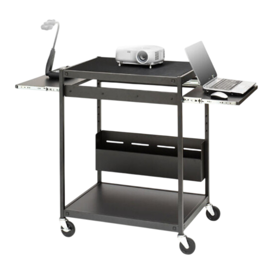
PRESENTATION CART WITH
AND WITHOUT POWER
PARTS LIST
Qty
Part#
Description
1
022-2695
Top Shelf w/ grommet hole
2
010-4780
Keyboard Shelves
1
010-3953
Bottom Shelf
2
010-4785
Slide Brackets
1
022-2692
Right Front Leg
1
022-2691
Left Front Leg
1
022-2694
Right Rear Leg
1
022-2693
Left Rear Leg
1
022-2309
Wire Tray
2
015-0002
4" Casters w/o Lock
2
015-0003
4" Casters w/ Lock
2
030-1191
14" Full Extension Slides
1
CFPS UNIT
Electrical Unit - TC12FF ONLY
Rear Legs - Stamped LR & RR
FIGURE 1
Lay the rear legs on a carpeted surface exactly as shown in FIGURE 1. (They are stamped "LR" & "RR") Slide
bottom shelf and top shelf onto the legs so that the brackets are inside the shelves as shown in FIGURE 2.
TC12 / TC12FF
Holes MUST
be ALIGNED
HARDWARE LIST
Ref
Qty
Part#
AA
16
030-0300-10T
BB
16
030-0002
CC
12
030-0325
DD
16
030-1228
EE
8
030-1203
GG
2
030-0302
HH
10
02236
I I
20
030-0240
1
010-1106
TOOLS REQUIRED
Hex Wrench (Provided)
Phillips Screwdriver
Rubber Mallet
STEP 1
Description
5/8" Square Head Bolts
5/16-18 Hex Serrated Nuts
1/4-20 x 1/2" Combo Screws
8-32 x 1/4" Combo Truss Hd Screws
#8-32 Acorn Nuts
#8-32 x 3/8" Screws - TC12FF ONLY
8-32 Hex Flange Nuts
1/4" External Lockwashers
Hex Wrench
FIGURE 2
Bracket MUST fit
INSIDE shelf
1
Advertisement

Related Manuals for Bretford TC12FF


Summary of Contents for Bretford TC12FF
- Page 1 TC12 / TC12FF PRESENTATION CART WITH AND WITHOUT POWER PARTS LIST Qty Part# Description 022-2695 Top Shelf w/ grommet hole 010-4780 Keyboard Shelves 010-3953 Bottom Shelf 010-4785 Slide Brackets 022-2692 Right Front Leg 022-2691 Left Front Leg 022-2694 Right Rear Leg 022-2693 Left Rear Leg 022-2309 Wire Tray 015-0002 4” Casters w/o Lock 015-0003 4” Casters w/ Lock 030-1191 14” Full Extension Slides CFPS UNIT Electrical Unit - TC12FF ONLY Rear Legs - Stamped LR & RR FIGURE 1 Lay the rear legs on a carpeted surface exactly as shown in FIGURE 1. (They are stamped “LR” & “RR”) Slide bottom shelf and top shelf onto the legs so that the brackets are inside the shelves as shown in FIGURE 2.
- Page 2 Holes MUST be ALIGNED Slide the front legs onto the shelves so that the brackets are inside the shelves as shown. NOTE: Make sure all bracket holes are aligned with the shelf holes. STEP 2 STEP 3 Secure shelves and legs together with bolts (AA) and nuts (BB) in each corner as shown.
- Page 3 STEP 4 Insert each caster into the bottom of each leg. If caster does not insert easily, use a rubber mallet to tap caster in place. Once caster are SECURELY in place, stand unit upright. STEP 5 Attach each slide bracket using screws (CC) and washers (I I) as shown. Note the position of the cart. One bracket is parallel with the back edge of the top shelf and the other one is parallel with the front edge of the top shelf.
- Page 4 NOTE: Separate slides by pulling on black tab. FIGURE 3 STEP 6 Separate each slide and attach outer slide piece (2 per bracket) to the slide brackets using screws (DD) and nuts (EE) as shown. NOTE: Slide may need to be extended some to align attachment holes. Slide cord bin between the rear legs as shown in FIGURE 3. Attach through the inside with screws (CC) and washers (I I) as shown in FIGURE 4. The pictures on the next page show how to achieve a fixed or an adjustable position. FIGURE 4 STEP 7...
- Page 5 SHELF FIXED POSITION Attach inner slide piece to keyboard shelf with screws (DD), washers (I I) and nuts (HH). CORD STEP 8 SHELF ADJUSTABLE POSITION CORD...
- Page 6 STEP 9 Slide each keyboard shelf into each side of the cart. STEP 10 FOR TC12FF ONLY Attach the CFPS electrical unit onto the cord bin slots with screws (GG) and nuts (HH). Part # 031-7452 Rev. 04.21.08 CZ...
Need help?
Do you have a question about the TC12FF and is the answer not in the manual?
Questions and answers