Table of Contents
Advertisement
Quick Links
Advertisement
Table of Contents

Related Manuals for ADLINK Technology DLAP-3000 Series


Summary of Contents for ADLINK Technology DLAP-3000 Series
- Page 1 DLAP-3000/3100-CF Series Embedded System supporting MXM Graphics Module with 8th/9th Generation Intel® Core™ i7/i5/i3 in LGA1151 Socket User’s Manual Manual Rev.: April 19, 2021 Revision Date: 50M-00019-1010 Part No: Leading EDGE COMPUTING...
- Page 2 Leading EDGE COMPUTING Revision History Revision Release Date Description of Change(s) 2020-12-23 Initial release Add MXM cooler for RTX5000 and 500W power supply; update 2021-04-19 specifications and DisplayPort BIOS settings...
- Page 3 DLAP-3000/3100-CF Preface Copyright © 2020, 2021 ADLINK Technology Inc. This document contains proprietary information protected by copy- right. All rights are reserved. No part of this manual may be repro- duced by any mechanical, electronic, or other means in any form without prior written permission of the manufacturer.
- Page 4 Leading EDGE COMPUTING California Proposition 65 Warning WARNING: This product can expose you to chemicals including acrylamide, arsenic, benzene, cadmium, Tris(1,3-dichloro-2-propyl) phosphate (TDCPP), 1,4- Dioxane, formaldehyde, lead, DEHP, styrene, DINP, BBP, PVC, and vinyl materials, which are known to the State of California to cause cancer, and acrylamide, benzene, cadmium, lead, mercury, phthalates, toluene, DEHP, DIDP, DnHP, DBP, BBP, PVC, and vinyl materials, which are known to the State of California to cause...
-
Page 5: Table Of Contents
DLAP-3000/3100-CF Table of Contents Preface ..................iii List of Tables................. vii List of Figures ................ ix 1 Introduction ................ 1 Overview................1 Features................1 Packing List ................. 2 Optional Accessories ............3 2 Specifications ..............5 DLAP-3000-CF ..............5 DLAP-3100-CF ..............11 DLAP-3000/3100-CF Functional Block Diagrams ..... - Page 6 Leading EDGE COMPUTING A Appendix: Power Consumption ........75 Power Consumption Reference ......... 75 B Appendix: Resource Mapping ..........77 BIOS Mapping in SPI ROM..........77 PCI/PCIe Devices .............. 78 IRQ Lines (APIC Mode) ............. 79 IRQ Lines (PIC Mode)............80 System Memory Mapping ..........81 System I/O Mapping ............
-
Page 7: List Of Tables
DLAP-3000/3100-CF List of Tables Table 2-1: Maximum Display Resolution ........19 Table 3-1: I/O Legend..............27 Table 3-2: Digital Input/Output Connector Pin Definition ... 29 Table 3-3: Active/Link LED Indicators........31 Table 3-4: Speed LED Indicators..........31 Table 3-5: D-Sub 9-pin Signal Function of COM Ports....32 Table 3-6: Mainboard Connector Legend ........ - Page 8 Leading EDGE COMPUTING This page intentionally left blank. viii List of Tables...
-
Page 9: List Of Figures
DLAP-3000/3100-CF List of Figures Figure 2-1: DLAP-3000-CF Functional Block Diagram ....17 Figure 2-2: DLAP-3100-CF Functional Block Diagram ....18 Figure 2-3: DLAP-3000-CF Front View ..........20 Figure 2-4: DLAP-3100-CF Front View ..........20 Figure 2-5: DLAP-3000/3100-CF Left Side View ......21 Figure 2-6: DLAP-3000/3100-CF Right Side View...... - Page 10 Leading EDGE COMPUTING This page intentionally left blank. List of Figures...
-
Page 11: Introduction
DLAP-3000/3100-CF Introduction 1.1 Overview The DLAP-3000/3100-CF series is an optimized computing plat- form supporting performance-hungry workloads, such as deep learning, with expandability options and active cooling for applica- tions requiring very high levels of computing in a limited space. The DLAP-3000/3100-CF series is one of the smallest embedded GPU platforms (3.2 liters) with a low TDP reliable MXM GPU design and scalable graphics processing ranging from Pascal to Turing GPUs. -
Page 12: Packing List
Leading EDGE COMPUTING 1.3 Packing List Before unpacking, check the shipping carton for any damage. If the shipping carton and/or contents are damaged, inform your dealer immediately. Retain the shipping carton and packing mate- rials for inspection. Obtain authorization from your dealer before returning any product to ADLINK. -
Page 13: Optional Accessories
DLAP-3000/3100-CF 1.4 Optional Accessories CPU cooler (P/N: 32-20495-0000) CPU cooler bracket (P/N: 32-50015-0100-A0) MXM cooler for P1000/P2000 (P/N: 32-20797-0200-A0) MXM cooler for P3000/P5000 (P/N: 32-20823-0020-A0) MXM cooler for T1000 (P/N: 32-20830-0200-A0) MXM cooler for RTX3000 (P/N: 32-20823-1100-A0) MXM cooler for RTX5000 (P/N: 32-20839-1000-A0) 12V/240W power adaptor (P/N: 31-62164-0010-A0) 500W power supply (12V/41.7A) (P/N: 91-95296-000E) Wall mount bracket set (P/N: 34-34546-0000-A0) (2 required) - Page 14 Leading EDGE COMPUTING This page intentionally left blank. Introduction...
-
Page 15: Specifications
DLAP-3000/3100-CF Specifications 2.1 DLAP-3000-CF DLAP- DLAP- DLAP- DLAP- DLAP- 3000-CFP1 3000-CFP2 3000-CFT1 3000-CFT3 3000-CFT5 Model DLAP-3000-CFP12* EGX-MXM- EGX-MXM- EGX-MXM- EGX-MXM- EGX-MXM- Support P1000 P2000 T1000 RTX3000 RTX5000 Intel® Core™ i7-9700E, 2.6GHz, 12M Cache, 65W TDP, LGA1151, DDR4 2666MHz support (8C/8T) Intel®... - Page 16 Leading EDGE COMPUTING DLAP- DLAP- DLAP- DLAP- DLAP- 3000-CFP1 3000-CFP2 3000-CFT1 3000-CFT3 3000-CFT5 Model DLAP-3000-CFP12* I/O Interface Display 6x DisplayPort (2 from CPU, 4 from MXM) Ethernet 1x GbE (Intel® i219-LM), 3x GbE (Intel® i210-AT) Serial Ports 1x RS-232/422/485, 1x RS-232 4x USB 3.2 Gen1 x1 ports, 4x USB 2.0 ports Default: w/o Audio Option 1: Mic-in, Line-out, Line-in...
- Page 17 DLAP-3000/3100-CF DLAP- DLAP- DLAP- DLAP- DLAP- 3000-CFP1 3000-CFP2 3000-CFT1 3000-CFT3 3000-CFT5 Model DLAP-3000-CFP12* Environmental Operating 0°C to 50°C (W/MXM, W/SSD, excluding EGX-MXM-RTX5000) Temperature 0°C to 40°C (EGX-MXM-RTX5000) Storage -20°C to 70°C Temperature Humidity 5% to 95%, non-condensing Operating: 2Grms, 5-500Hz, 3 axes Vibration Package (non operating): 3.44Grms, 10-1000Hz, 3 axes (w/ MXM, w/SSD)
- Page 18 Leading EDGE COMPUTING DLAP-3000-CFP3 DLAP-3000-CFP5 Model DLAP-3000-CFP35* MXM Support EGX-MXM-P3000 EGX-MXM-P5000 Intel® Core™ i7-9700E, 2.6GHz, 12M Cache, 65W TDP, LGA1151, DDR4 2666MHz support (8C/8T) Intel® Core™ i7-9700TE, 1.8GHz, 12M Cache, 35W TDP, LGA1151, DDR4 2666MHz support (8C/8T) Intel® Core™ i5-9500E, 3.0GHz, 9M Cache, 65W TDP, LGA1151, DDR4 2666MHz support (6C/6T) Intel®...
- Page 19 DLAP-3000/3100-CF DLAP-3000-CFP3 DLAP-3000-CFP5 Model DLAP-3000-CFP35* I/O Interface Display 6x DisplayPort (2 from CPU, 4 from MXM) Ethernet 1x GbE (Intel® i219-LM), 3x GbE (Intel® i210-AT) Serial Ports 1x RS-232/422/485, 1x RS-232 4x USB 3.2 Gen1 x1 ports, 4x USB 2.0 ports Default: w/o Audio Option 1: Mic-in, Line-out, Line-in Audio...
- Page 20 Leading EDGE COMPUTING DLAP-3000-CFP3 DLAP-3000-CFP5 Model DLAP-3000-CFP35* Environmental 0°C to 50°C (W/MXM, W/SSD, excluding EGX-MXM- Operating RTX5000) Temperature 0°C to 40°C (EGX-MXM-RTX5000) Storage -20°C to 70°C Temperature Humidity 5% to 95%, non-condensing Operating: 2Grms, 5-500Hz, 3 axes Vibration Package (non operating): 3.44Grms, 10-1000Hz, 3 axes (w/ MXM, w/SSD) Operating and Package (non operating): 30G, 11ms duration, Shock...
-
Page 21: Dlap-3100-Cf
DLAP-3000/3100-CF 2.2 DLAP-3100-CF DLAP- DLAP- DLAP- DLAP- DLAP- 3100-CFP1 3100-CFP2 3100-CFT1 3100-CFT3 3100-CFT5 Model DLAP-3100-CFP12* EGX-MXM- EGX-MXM- EGX-MXM- EGX-MXM- EGX-MXM- Support P1000 P2000 T1000 RTX3000 RTX5000 Intel® Core™ i7-9700E, 2.6GHz, 12M Cache, 65W TDP, LGA1151, DDR4 2666MHz support (8C/8T) Intel® Core™ i7-9700TE, 1.8GHz, 12M Cache, 35W TDP, LGA1151, DDR4 2666MHz support (8C/8T) Intel®... - Page 22 Leading EDGE COMPUTING DLAP- DLAP- DLAP- DLAP- DLAP- 3100-CFP1 3100-CFP2 3100-CFT1 3100-CFT3 3100-CFT5 Model DLAP-3100-CFP12* I/O Interface Display 6x DisplayPort (2 from CPU, 4 from MXM) Ethernet 1x GbE (Intel® i219-LM), 5x GbE (Intel® i210-AT) Serial Ports 1x RS-232/422/485, 1x RS-232 6x USB 3.2 Gen1 x1 ports, 2x USB 2.0 ports Audio Mic-in, L/R speaker-out (6W + 6W)
- Page 23 DLAP-3000/3100-CF DLAP- DLAP- DLAP- DLAP- DLAP- 3100-CFP1 3100-CFP2 3100-CFT1 3100-CFT3 3100-CFT5 Model DLAP-3100-CFP12* Environmental Operating 0°C to 50°C (W/MXM, W/SSD, excluding EGX-MXM-RTX5000) Temperature 0°C to 40°C (EGX-MXM-RTX5000) Storage -20°C to 70°C Temperature Humidity 5% to 95%, non-condensing Operating: 2Grms, 5-500Hz, 3 axes Vibration Package (non operating): 3.44Grms, 10-1000Hz, 3 axes (w/ MXM, w/SSD)
- Page 24 Leading EDGE COMPUTING DLAP-3100-CFP3 DLAP-3100-CFP5 Model DLAP-3100-CFP35* EGX-MXM-P3000 EGX-MXM-P5000 Support Intel® Core™ i7-9700E, 2.6GHz, 12M Cache, 65W TDP, LGA1151, DDR4 2666MHz support (8C/8T) Intel® Core™ i7-9700TE, 1.8GHz, 12M Cache, 35W TDP, LGA1151, DDR4 2666MHz support (8C/8T) Intel® Core™ i5-9500E, 3.0GHz, 9M Cache, 65W TDP, LGA1151, DDR4 2666MHz support (6C/6T) Intel®...
- Page 25 DLAP-3000/3100-CF DLAP-3100-CFP3 DLAP-3100-CFP5 Model DLAP-3100-CFP35* I/O Interface Display 6x DisplayPort (2 from CPU, 4 from MXM) Ethernet 1x GbE (Intel® i219-LM), 5x GbE (Intel® i210-AT) Serial Ports 1x RS-232/422/485, 1x RS-232 6x USB 3.2 Gen1 x1 ports, 2x USB 2.0 ports Audio Mic-in, L/R speaker-out (6W + 6W) 1x M.2 E key supporting 1630 or 2230 for Wi-Fi/BT module...
- Page 26 Leading EDGE COMPUTING DLAP-3100-CFP3 DLAP-3100-CFP5 Model DLAP-3100-CFP35* Environmental Operating 0°C to 50°C (W/MXM, W/SSD, excluding EGX-MXM-RTX5000) Temperature 0°C to 40°C (EGX-MXM-RTX5000) Storage -20°C to 70°C Temperature Humidity 5% to 95%, non-condensing Operating: 2Grms, 5-500Hz, 3 axes Vibration Package (non operating): 3.44Grms, 10-1000Hz, 3 axes (w/ MXM, w/SSD) Operating and Package (non operating): 30G, 11ms duration, Shock...
-
Page 27: Dlap-3000/3100-Cf Functional Block Diagrams
DLAP-3000/3100-CF 2.3 DLAP-3000/3100-CF Functional Block Diagrams 2.3.1 DLAP-3000-CF Functional Block Diagram SODIMM 1 DDI 1 (PORT B) : DP DP CN Channel A DDR4 non-ECC Socket DP CN DDI 2 (PORT C) : DP 8th/9th Gen Intel® DDI 3 (PORT D) : HDMI HDMI CN SODIMM 2 Core™... -
Page 28: Figure 2-2: Dlap-3100-Cf Functional Block Diagram
Leading EDGE COMPUTING 2.3.2 DLAP-3100-CF Functional Block Diagram SODIMM 1 DDI 1 (PORT B) : DP DP CN Channel A DDR4 non-ECC Socket DP CN DDI 2 (PORT C) : DP 8th/9th Gen Intel® DDI 3 (PORT D) : HDMI HDMI CN SODIMM 2 Core™... -
Page 29: Display Options
DLAP-3000/3100-CF 2.4 Display Options The DLAP-3000/3100-CF includes six DisplayPort connectors, two DisplayPort signals from the CPU and four from MXM. All Dis- playPorts support DP++. Use DisplayPort1 (DP 1) to connect a monitor when booting the system for the first time to properly access the display settings in the BIOS menu. -
Page 30: Mechanical Dimensions
Leading EDGE COMPUTING 2.5 Mechanical Dimensions units: mm Figure 2-3: DLAP-3000-CF Front View (including wall-mount brackets and footpads) units: mm Figure 2-4: DLAP-3100-CF Front View (including footpads) Specifications... -
Page 31: Figure 2-5: Dlap-3000/3100-Cf Left Side View
DLAP-3000/3100-CF units: mm Figure 2-5: DLAP-3000/3100-CF Left Side View units: mm Figure 2-6: DLAP-3000/3100-CF Right Side View Specifications... -
Page 32: Figure 2-7: Dlap-3000-Cf Rear View
Leading EDGE COMPUTING units: mm Figure 2-7: DLAP-3000-CF Rear View This page intentionally left blank. units: mm Figure 2-8: DLAP-3100-CF Rear View Specifications... -
Page 33: Figure 2-9: Dlap-3000/3100-Cf Top View
DLAP-3000/3100-CF units: mm 6.50 Figure 2-9: DLAP-3000/3100-CF Top View To prevent damage to the system, ensure there is a minimum 10 cm clearance around the air vents for unrestricted airflow. The air tempera- ture inside the enclosure could rise above the specified operating temper- WARNING: ature limits if the airflow through the vents is restricted. - Page 34 Leading EDGE COMPUTING This page intentionally left blank. Specifications...
-
Page 35: System Layout
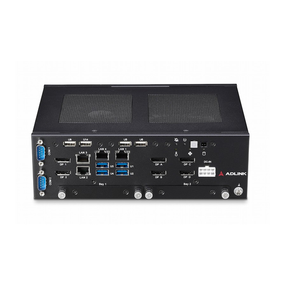
DLAP-3000/3100-CF System Layout 3.1 Front Panel The DLAP-3000/3100-CF Series provides the following I/O access features. Figure 3-1: DLAP-3000-CF Front Panel I/O Figure 3-2: DLAP-3000-CF Rear Panel I/O System Layout... -
Page 36: Figure 3-3: Dlap-3100-Cf Front Panel I/O
Leading EDGE COMPUTING Figure 3-3: DLAP-3100-CF Front Panel I/O Figure 3-4: DLAP-3100-CF Rear Panel I/O System Layout... -
Page 37: Table 3-1: I/O Legend
DLAP-3000/3100-CF DisplayPort from MXM for USB 2.0 Type-A x2 (U9, U14) DP C/DP D USB 3.2 Gen1 x1 Type-A x2 for U5/U6 (DLAP-3100-CF), J 12V DC Power Input USB 2.0 (DLAP-3000-CF) RS-232 for COM1, i210-AT (LAN 5/LAN 6), RS-232/422/485 for COM2 (DLAP-3100-CF only) 2x 2.5”... - Page 38 Leading EDGE COMPUTING Alarm Reset Button: When the fan or GPU temperature alarm has been triggered, insert a small, thin object like a paper clip and press the reset button to turn off the alarm. This is to reset the alarm beeper only, not to reset the alarm LED.
-
Page 39: Table 3-2: Digital Input/Output Connector Pin Definition
DLAP-3000/3100-CF 3.1.3 Digital I/O Connector The DLAP-3000/3100-CF provides 4 channels of non-isolation digital input and 4 channels of non-isolation digital output circuits, with specificacations and circuits as follows. 4-channel Digital Input VIH: 1.5 to 5V VIL: 0 to 0.5V 4-channel Digital Output Output type: Open drain N-channel MOSFET driver with internal pull high of 200Ω... -
Page 40: Figure 3-7: Digital Input Circuit
Leading EDGE COMPUTING Figure 3-7: Digital Input Circuit 2.2K Figure 3-8: Digital Output Circuit System Layout... -
Page 41: Table 3-3: Active/Link Led Indicators
DLAP-3000/3100-CF 3.1.4 Gigabit Ethernet Ports LED Color Status Description Ethernet port is disconnected. Orange Ethernet port is connected with no activity. Flashing Ethernet port is connected and active. Table 3-3: Active/Link LED Indicators LED Color Status Description 10 Mbps Green/Orange Green 100 Mbps Orange... -
Page 42: Table 3-5: D-Sub 9-Pin Signal Function Of Com Ports
Leading EDGE COMPUTING 3.1.5 COM Port Connectors The DLAP-3000/3100-CF provides two COM ports through D-sub 9-pin connectors. The COM2 port support RS-232/422/485 modes by BIOS setting, while COM1 supports only RS-232. Figure 3-9: COM Port Pin Definition Signal Name RS-232 RS-422 RS-485 DCD#... -
Page 43: Internal I/O Connectors
DLAP-3000/3100-CF 3.2 Internal I/O Connectors Installation of add-on devices must be carried out by ADLINK service personnel only. Users must not disassemble the device themselves. WARNING: 3.2.1 Mainboard Connector Locations AH AI Figure 3-10: Mainboard Connectors (Top) System Layout... -
Page 44: Figure 3-11: Mainboard Connectors (Rear)
Leading EDGE COMPUTING Figure 3-11: Mainboard Connectors (Rear) CPU socket DRAM socket for DIMM1 DRAM socket for DIMM2 CPU Fan connector System Fan connector 2x USB 2.0 Gen1 x1 pin header for U9/U14 RS-232 pin header for COM1 RS-232/422/485 pin header for COM2 2x USB 3.2 Gen1 x1 pin header for U5/U6 (DLAP-3100-CF) or 2x USB 2.0 pin header for U5/U6 (DLAP-3000-CF) Multi I/O connector... -
Page 45: Table 3-6: Mainboard Connector Legend
DLAP-3000/3100-CF PCIe power connector SATA connector SATA connector SATA power connector Power-on module connector DIO connector MXM connector PCB edge connector RTC battery connector GPU fan connector 12V DC in connector DisplayPort C and D from MXM DisplayPort A and B from MXM LAN 1 and USB 3.2 Gen 1 x1 ports 1 and 2 AA LAN 4 and USB 3.2 Gen 1 x1 ports 3 and 4 AB LAN 2 and LAN 3... - Page 46 Leading EDGE COMPUTING 3.2.2 BMC Status LED and WDT LED 3.2.2.1 Status LED (Blue) The Status LED is controlled by SEMA to signal system state changes and power up failures. The system state changes can be HW-Reset, SW-Reset, Power-Up, Power-Down, Reset-Button and Power-Button activity.
-
Page 47: Table 3-7: Usb 2.0 Connector Pin Definition
DLAP-3000/3100-CF 3.2.3 USB 2.0 Connector One USB 2.0 pin header is provided on the mainboard for an inter- nal USB dongle. Figure 3-12: USB 2.0 Connector Pin Definition Signal Signal P5V_USB1 CN_U2_USB14_P P5V_USB1 CN_U2_USB9_N CN_U2_USB14_N CN_U2_USB9_P Table 3-7: USB 2.0 Connector Pin Definition System Layout... -
Page 48: Table 3-8: Usb 3.2 Connector Pin Definition
Leading EDGE COMPUTING 3.2.4 USB 3.2 Connector One USB 3.2 Gen1 x1pin header is provided on the mainboard for an internal USB dongle. Figure 3-13: USB 3.2 Connector Pin Definition Signal Signal P5V_USB56 CN_U3_USB6_T_P CN_U2_USB5_N CN_U3_USB6_T_N CN_U2_USB5_P CN_U3_USB6_R_P CN_U3_USB5_R_N CN_U3_USB6_R_N CN_U3_USB5_R_P CN_U2_USB6_P CN_U3_USB5_T_N... -
Page 49: Table 3-9: Pcie Power Connector Pin Definition
DLAP-3000/3100-CF 3.2.5 PCIe Power Connector Figure 3-14: PCIe Power Connector Pin Definition Signal P_+12V_S P_+12V_S P_+5V0_S P_+5V0_S Table 3-9: PCIe Power Connector Pin Definition 3.2.6 SATA Power Connector Figure 3-15: SATAConnector Pin Definition Signal P_+5V0_S P_+5V0_S P_+5V0_S Table 3-10: SATA Connector Pin Definition System Layout... -
Page 50: Table 3-11: Com Connector Pin Definition
Leading EDGE COMPUTING 3.2.7 COM Connector Figure 3-16: COM Connector Pin Definition Signal Name RS-232 RS-422 RS-485 DCD# Tx/Rx- DSR# Tx/Rx+ RTS# CTS# DTR# Table 3-11: COM Connector Pin Definition System Layout... -
Page 51: Table 3-12: Cpu/System Fan Connector Pin Definition
DLAP-3000/3100-CF 3.2.8 CPU/System Fan Connectors Two connectors are provided for CPU and system fan power. Figure 3-17: CPU/System Fan Connector Pin Definition Signal FAN_GND P_+12V_FAN FAN_IN FAN_OUT Table 3-12: CPU/System Fan Connector Pin Definition System Layout... -
Page 52: Table 3-13: Gpu Fan Connector Pin Definition
Leading EDGE COMPUTING 3.2.9 GPU Fan Connector Figure 3-18: GPU Fan Connector Pin Definition Signal FAN_OUT FAN_IN P_+12V_FAN FAN_GND Table 3-13: GPU Fan Connector Pin Definition System Layout... -
Page 53: Table 3-14: Audio Connector Pin Definition
DLAP-3000/3100-CF 3.2.10 Audio Connector Figure 3-19: Audio Connector Pin Definition Signal Signal AUDIO_Sense GND_AUD SPK_RP A_MIC_IN_L A_L_IN_L SPK_LP SPK_RN A_MIC_IN_R A_L_IN_R SPK_LN Table 3-14: Audio Connector Pin Definition System Layout... -
Page 54: Table 3-15: Com1 Rs-232/Cctalk Selection Jumper
Leading EDGE COMPUTING 3.2.11 Multiple I/O Connector Figure 3-20: Multiple I/O Connector Pin Definition 3.2.11.1 COM1 RS-232/CCtalk Selection Jumper RS-232/CCtalk RS-232 (default) 8-10 CCtalk 9-11 10-12 Table 3-15: COM1 RS-232/CCtalk Selection Jumper 3.2.11.2 Case Open Jumper Case open 13-14 Function ON Undo (default) Table 3-16: Case Open Jumper 3.2.11.3... -
Page 55: Table 3-18: Clear Cmos Jumper
DLAP-3000/3100-CF 3.2.11.4 Clear CMOS Jumper Clear CMOS 17-18 Clear CMOS Undo (default) Table 3-18: Clear CMOS Jumper 3.2.11.5 BIOS WP Jumper BIOS WP 17-18 BIOS WP Undo (default) Table 3-19: BIOS WP Jumper S3 and S4 not supported under operating system. IAMT is not supported while pairing with Q370. -
Page 56: Table 3-20: Power-On Module Connector Pin Definition
Leading EDGE COMPUTING 3.2.12 Power-on Module Connector Figure 3-21: Power-on Module Connector Pin Definition Signal Signal P_+5V0_A LED_TEMP_ALARM P_+3V3_A PWR_BTN LED_FAN_ALARM LED_STANDBY RST_BTN# P_+12V_A POWER_ON RESET_BUTTON_ALARM# BEEP_TEMP_ALARM PCH_SATS-L Table 3-20: Power-on Module Connector Pin Definition System Layout... -
Page 57: Table 3-21: Dio Connector Pin Definition
DLAP-3000/3100-CF 3.2.13 DIO Connector Figure 3-22: DIO Connector Pin Definition Signal 5V_12V_S Table 3-21: DIO Connector Pin Definition System Layout... -
Page 58: Table 3-22: 12V Dc-In Connector Pin Definition
Leading EDGE COMPUTING 3.2.14 12V DC-in Connector Figure 3-23: 12V DC-in Connector Pin Definition Signal Signal DCIN DCIN DCIN DCIN Table 3-22: 12V DC-in Connector Pin Definition Before providing DC power, ensure the voltage and polarity provided are compatible with the DC input. Improper input volt- age and/or polarity can be responsible for system damage. -
Page 59: Figure 3-24: Pcb Edge Connector Pin Definition
DLAP-3000/3100-CF 3.2.15 PCB Edge Connector Figure 3-24: PCB Edge Connector Pin Definition Signal A1 (Pin 1 on bottom) P_+12V_S P_+12V_S JTAGE_CLK(NC) JTAGE_DI(NC) JTAGE_DO(NC) JTAGE_MS(NC) P_+3V3_S P_+3V3_S PCH_PLTRST-L_BUF CLKOUT_PCIE_P7 CLKOUT_PCIE_N7 GF_PCIEX21_RX_P GF_PCIEX21_RX_N GF_PCIEX22_RX_P System Layout... - Page 60 Leading EDGE COMPUTING Signal GF_PCIEX22_RX_N GF_PCIEX23_RX_P GF_PCIEX23_RX_N GF_PCIEX24_RX_P GF_PCIEX24_RX_N GF_PCIEX1_RX_P GF_PCIEX1_RX_N GF_PCIEX2_RX_P GF_PCIEX2_RX_N GF_PCIEX3_RX_P GF_PCIEX3_RX_N GF_PCIEX4_RX_P GF_PCIEX4_RX_N B1 (Pin 1 on top) P_+12V_S P_+12V_S P_+12V_S PCH_SMB_CLK_A System Layout...
- Page 61 DLAP-3000/3100-CF Signal PCH_SMB_DAT_A P_+3V3_S JTAGE_RST(NC) P_+3V3_S X_PCIE_WAKE-L GF_PCIEX5_21_TX_P GF_PCIEX5_21_TX_N PCH_CLK_REQ7-L GF_PCIEX22_TX_P GF_PCIEX22_TX_N GF_PCIEX23_TX_P GF_PCIEX23_TX_N GF_PCIEX24_TX_P GF_PCIEX24_TX_N PCH_CLK_REQ7-L GF_PCIEX1_TX_P GF_PCIEX1_TX_N GF_PCIEX2_TX_P GF_PCIEX2_TX_N System Layout...
-
Page 62: Table 3-23: Pcb Edge Connector Pin Definition
Leading EDGE COMPUTING Signal GF_PCIEX3_TX_P GF_PCIEX3_TX_N GF_PCIEX4_TX_P GF_PCIEX4_TX_N PCH_CLK_REQ7-L Table 3-23: PCB Edge Connector Pin Definition 3.2.16 DB40 Connector Figure 3-25: DB40 Connector Pin Definition Signal VCC_SPI_IN SPI_BIOS_CS0# SPI_BIOS_CS1# SPI_BIOS_MISO SPI_BIOS_MOSI SPI_BIOS_CLK 3V3_LPC BIOS_DIS0 System Layout... -
Page 63: Table 3-24: Db40 Connector Pin Definition
DLAP-3000/3100-CF Signal RST# CLK33_LPC LPC_FRAME# LPC_AD3 LPC_AD2 LPC_AD1 LPC_AD0 3.3V_SMC 3.3V_A TXD6 RXD6 FUMD0 RESET_IN# DATA OCD0A OCD0B PWRBTN# SYS_RESET# CB_RESET# CB_PWROK SUS_S3# SUS_S4# SUS_S5# POSTWDT_DIS# SEL_BIOS BIOS_MODE SMC_STATUS RESVD Table 3-24: DB40 Connector Pin Definition System Layout... - Page 64 Leading EDGE COMPUTING This page intentionally left blank. System Layout...
-
Page 65: Getting Started
DLAP-3000/3100-CF Getting Started This chapter outlines the procedures for 2.5" storage, M.2 module, MXM module, wall-mount brackets, and driver installation. Installation of an add-on device must be carried out by ADLINK service personnel only. Users must not disassemble the device themselves. -
Page 66: Installing 2.5" Storage
Leading EDGE COMPUTING 4.1 Installing 2.5” Storage Before installing a disk drive, the drive bracket must be removed. 1. Remove the thumbscrews and take out the 2.5” drive bay. Getting Started... - Page 67 DLAP-3000/3100-CF 2. Place a 2.5” SSD up to 9mm thick into the bracket and use the 4 provided M3 screws at 4kgf/cm torque to attach the drive to the bracket. 3. Gently slide the bracket back into the drive bay until the SATA connector on the PCB is engaged, and then refas- ten the thumbscrews.
-
Page 68: Installing An M.2 Module
Leading EDGE COMPUTING 4.2 Installing an M.2 Module Remove the bottom panel before installing an M.2 Module. 1. Remove 8 screws total to release the bottom panel from the chassis, 4 on the bottom, and 2 each on the left and right sides. - Page 69 DLAP-3000/3100-CF Left side screws Right side screws Getting Started...
- Page 70 Leading EDGE COMPUTING 2. Remove the 4 screws attaching the left drive bay to the chassis. Getting Started...
- Page 71 DLAP-3000/3100-CF 3. Move the drive bay to reveal the M.2 socket underneath and install an M.2 module with an M3 screw at 4kgf/cm torque. P/N: 33-03013-0040. 4. Reattach the drive bay, and then screw the bottom panel back on to complete the installation at 6kgf/cm torque. Getting Started...
-
Page 72: Installing Mxm P1000/P2000/T1000 Module
Leading EDGE COMPUTING 4.3 Installing MXM P1000/P2000/T1000 Module 1. Remove the protective film from the MXM cooler. Getting Started... - Page 73 DLAP-3000/3100-CF 2. Attach the MXM cooler to the MXM module. Tighten the screws in the order indicated at 4kgf/cm torque. Getting Started...
- Page 74 Leading EDGE COMPUTING 3. Remove 2 screws to detach the top panel from the chas- sis. Remove the top panel to reveal the internal compo- nents of the system. Getting Started...
- Page 75 DLAP-3000/3100-CF 4. Attach the MXM module with 2 M3 screws P/N: 33- 03306-0040 at 4kgf/cm torque and plug the MXM cooling fan connector into the GPU fan connector. 5. Screw the top panel back on to complete the installation. Getting Started...
-
Page 76: Installing Mxm P3000/P5000/Rtx3000/Rtx5000 Module
Leading EDGE COMPUTING 4.4 Installing MXM P3000/P5000/RTX3000/RTX5000 Module 1. Remove 2 screws to detach the top panel from the chassis. Getting Started... - Page 77 DLAP-3000/3100-CF 2. Remove the top panel to reveal the internal components of the system. Getting Started...
- Page 78 Leading EDGE COMPUTING 3. Remove the protective film from the MXM cooler bracket and attach the bracket to the bottom side of the MXM module. Getting Started...
- Page 79 DLAP-3000/3100-CF 4. Attach the MXM module with 2 M3 screws P/N: 33- 03306-0040 at 4kgf/cm torque to the mainboard. Getting Started...
- Page 80 Leading EDGE COMPUTING 5. Remove the protective film from the MXM cooler and lock the MXM cooler on the MXM module via the four spring screws. Then plug the MXM cooling fan connector into the GPU fan connector. Getting Started...
- Page 81 DLAP-3000/3100-CF 6. Place 4 washers PN: 33-90086-0000-A0 and 4 rubber spacers PN: 39-00039-0000 over the screw holes on the top of the fan. 7. Use 4 screws PN: 33-03320-0050 to secure the rubber spacers to the fan at 4kgf/cm torque. 8.
-
Page 82: Mounting
Leading EDGE COMPUTING 4.5 Mounting 4.5.1 Install the Wall-mount Brackets Use the 4 footpad screws to attach the 2 wall-mount brackets to the chassis. Utilisez les 4 incluses dans la boîte d'accessoires pour fixer les 2 supports de montage mural inclus au châssis. Getting Started... - Page 83 DLAP-3000/3100-CF Mounting the Device / Montage de l'Appareil Mount the device to a wall using the 4 keyhole openings indicated with M4 6mm screws torqued to 6kgf/cm, or the 6 mounting holes circled, according to the spacing dimensions of the holes in the bracket as shown in Figure 2-9 DLAP-3000/3100-CF Top View.
-
Page 84: Driver Installation
Leading EDGE COMPUTING 4.6 Driver Installation Download the Windows 10 drivers from the product page at https://www.adlinktech.com/Products/Industrial_PCs_Fanless_ Embedded_PCs/IPCSystems/DLAP-3100-CF_Series. The following drivers must be installed: Intel GPU Chipset Audio DIO (DLAP-3100-CF only) RAID (DLAP-3100-CF only) Getting Started... -
Page 85: A Appendix: Power Consumption
DLAP-3000/3100-CF Appendix A Power Consumption Information in this Appendix is for power budget planning and design purposes only. Actual power consumption may differ based on final application. NOTE: NOTE: A.1 Power Consumption Reference Power consumption as follows is based on lab data in which 12V DC is applied and current is measured by the DC power supply. -
Page 86: Table A-2: Dlap-3100 Power Consumption
Leading EDGE COMPUTING DLAP-3100 Power Consumption 65W CPU/RTX5000 Full loading 275W 65W CPU/RTX3000 Full loading 245W 65W CPU/T1000 Full loading 215W 65W CPU/P5000 Full loading 265W 65W CPU/P3000 Full loading 240W 65W CPU/P2000 Full loading 223W 65W CPU/P1000 Full loading 212W 35W CPU/RTX5000 Full loading 245W... -
Page 87: B Appendix: Resource Mapping
DLAP-3000/3100-CF Appendix B Resource Mapping B.1 BIOS Mapping in SPI ROM The chipset supports up to three SPI ROMs (SPI_CS0#, SPI_CS1# and SPI_CS2#). The motherboard uses SPI flash SPI_CS0# to select the SPI flash which stores ME firmware and the system BIOS. The size of the SPI ROM is 16MB for H310, and 32MB for Q370 chipsets. -
Page 88: Pci/Pcie Devices
Leading EDGE COMPUTING B.2 PCI/PCIe Devices The following table lists all PCI/PCIe devices in the system. Device Function Routing Description Number Number Number 0x00 Intel HOST Bridge - 6 Cores/Desktop 0x02 Internal IGFX - GT2/6 Cores/Desktop 0x01 Internal PEG Root Port D1F0 0x12 Internal Thermal Subsystem... -
Page 89: Irq Lines (Apic Mode)
DLAP-3000/3100-CF B.3 IRQ Lines (APIC Mode) The following table lists the IRQ line mapping when APIC mode is enabled. Typical Interrupt IRQ # Connected to Pin Available Resource Counter 0 Keyboard Controller Cascade Interrupt from slave PIC Serial Port 2 (COM2) IRQ3 via SERIRQ/PIRQ Serial Port 1 (COM1) IRQ4 via SERIRQ/PIRQ IRQ5 via SERIRQ/PIRQ IRQ6 via SERIRQ/PIRQ... -
Page 90: Irq Lines (Pic Mode)
Leading EDGE COMPUTING B.4 IRQ Lines (PIC Mode) The following table lists the IRQ line mapping when APIC mode is disabled. Typical Interrupt IRQ # Connected to Pin Available Resource Counter 0 Keyboard Controller Cascade Interrupt from slave PIC Serial Port 2 (COM2) IRQ3 via SERIRQ/PIRQ See note. -
Page 91: System Memory Mapping
DLAP-3000/3100-CF B.5 System Memory Mapping The following table lists the system memory mapping. Address Range Address Range (Hex) Size Description (Decimal) (4GB – 2MB) FFE00000 – FFFFFFFF 2 MB High BIOS Area (4GB – 18MB) – FEE00000 – FEEFFFFF 1 MB MSI Interrupt (4GB –17MB –... -
Page 92: System I/O Mapping
Leading EDGE COMPUTING B.6 System I/O Mapping The following table lists the system I/O mapping. I/O Range (Hex) Device 020h – 02Dh & 030h – 03Dh Interrupt controller 1, 8259 equivalent 02Eh – 02Fh Motherboard resource 040h – 043h & 050h – 053h System Timer 04Eh –... -
Page 93: Pci/Pcie Interrupt Routing Mapping
DLAP-3000/3100-CF B.7 PCI/PCIe Interrupt Routing Mapping B.7.1 Internal Devices Audio xHCI SATA SMBus INT Line Controller Controller Controller #1 Controller Controller Controller Int0 INTA: 16 INTA: 16 INTA: 16 INTA: 16 INTA: 16 INTA: 16 Int1 INTB: 17 INTB: 17 INTB: 17 Int2 INTC: 18... -
Page 94: Smbus Slave Address Mapping
Leading EDGE COMPUTING B.8 SMBus Slave Address Mapping The following table lists the SMBus slave address (8-bit address- ing) mapping. Device Address DIMM A 0A0h DIMM B 0A4h 050h 0C0h Resource Mapping... -
Page 95: C Appendix: Bios Setup
DLAP-3000/3100-CF Appendix C BIOS Setup BIOS can be configured via the BIOS Setup Utility that is invoked during BIOS boot phase. The BIOS configuration is kept in NVRAM which is the same hardware part where the BIOS is stored. All settings will remain after the system is powered down. C.1 BIOS Setup Menu The BIOS Setup Utility is invoked by pressing <ESC>... - Page 96 Leading EDGE COMPUTING Menu Conventions The appearance of the setup menus and items listed in this chapter are based on a VT100 terminal connection via serial console with the following menu conventions. Using color The default BIOS setup fields are in black. The BIOS setup fields currently not used are in grey.
-
Page 97: Menu Structure
DLAP-3000/3100-CF C.2 Menu Structure This section presents the six primary menus of the BIOS Setup Utility. Use the following tables as a quick reference for the contents of the BIOS Setup Utility. The remainder of this chapter describe the submenus and options for each menu item. The default settings are presented in bold, and the function of each setting is described in the right hand column of the table. - Page 98 Leading EDGE COMPUTING Boot Save & Exit - Boot Configuration - Save Changes and Exit - Setup Prompt Timeout - Discard Changes and Exit - Bootup NumLock State - Save Changes and Reset - Quiet Boot - Discard Changes and Reset - Fast Boot - Save Changes - Boot Order...
-
Page 99: Main Menu
DLAP-3000/3100-CF C.3 Main Menu This menu provides read-only information about your system and also allows you to set the System Date and Time. Refer to the tables below for details of the submenus and settings. C.3.1 Main > BIOS Information Feature Options Description... - Page 100 Leading EDGE COMPUTING C.3.4 Main > Memory Information Feature Options Description Total Memory Info only Total Memory Memory Frequency Info only Memory Frequency C.3.5 Main > PCH Information Feature Options Description PCH SKU Info only PCH SKU Stepping Info only PCH Stepping C.3.6 Main >...
- Page 101 DLAP-3000/3100-CF C.3.8 Main > System Date & Time Feature Options Description Requires the alpha-numeric entry of Weekday, the day of the week, day of the System Date MM/DD/ month, calendar month, and all 4 YYYY digits of the year, indicating the century and year (Fri XX/XX/20XX) Presented as a 24-hour clock setting System Time...
-
Page 102: Advanced Menu
Leading EDGE COMPUTING C.4 Advanced Menu This menu contains the settings for most of the user interfaces in the system. C.4.1 Advanced > CPU Configuration Feature Options Description CPU Configuration Info only Type Info only Displays the Processor Type Package Info only Displays the Processor Package Stepping... - Page 103 DLAP-3000/3100-CF Feature Options Description Intel(R) Disabled Allows more than two frequency ranges to SpeedStep(tm) be supported. Enabled Intel(R) Speed Shift Disabled Enables/Disables Intel(R) Speed Shift Technology Technology support. Enabling will expose Enabled the CPPC v2 interface to allow for hardware controlled P-states.
- Page 104 Leading EDGE COMPUTING Feature Options Description Tcc Activation Offset 0-63 Offset from factory set Tcc activation temprature at which the Thermal Control Default: 1 Circuit must be activated. Tcc will be activated at: Tcc Activation Temp - Tcc Activation Offset. Tcc Activation Offset range is 0 to 63.
- Page 105 DLAP-3000/3100-CF Feature Options Description Data format and Color Data format and Color Depth VESA 24 bpp Depth JEIDA 24 bpp select JEIDA/vesa 18 bpp LVDS Output Mode Single/Dual mode select Dual LVDS bus Single LVDS bus DE Polarity DE Polarity select Active High Active Low Vsync Polarity...
- Page 106 Leading EDGE COMPUTING Feature Options Description Lock Legacy Resources Disabled Enables/Disables Lock of Enabled Legacy Resources Restore AC Power Loss Power On Select AC power state when Power Off power is re-applied after a power failure. Last State Power Supply Unit Emulate AT Mode ATX: OS will turn off system power when shutdown.
- Page 107 DLAP-3000/3100-CF C.4.5 Advanced > System Management Feature Options Description System Management Info only Version Info only SEMA Firmware Info only Version of SEMA Firmware Build Date Info only Build Date of SEMA Firmware SEMA Bootloader Info only Version of SEMA Bootloader Build Date Info only Build Date of SEMA Bootloader...
- Page 108 Leading EDGE COMPUTING Feature Options Description AT/ATX mode Info only AT/ATX mode ACPI Thermal Trigger Info only ACPI Thermal Trigger Backlight restore Info only Backlight restore DTS register available Info only DTS register available System Fan 2 Info only System Fan 2 TIVA BMC Info only TIVA BMC Board2 Temperature...
- Page 109 DLAP-3000/3100-CF C.4.10 Advanced > Thermal Management Feature Options Description Thermal Management Info only Info only CPU Temperature Current Info only Current CPU temperature Startup Info only Startup CPU temperature Info only Min. CPU temperature Info only Max. CPU temperature Info only Board Temperatures Current Info only...
- Page 110 Leading EDGE COMPUTING C.4.11 Advanced > Thermal Management > Smart Fan Feature Options Description Smart Fan Info only CPU Smart FanTemperature CPU Smart CPU Sensor Source FanTemperature Source CPU Fan Mode CPU Fan Mode AUTO (Smart Fan) Fan Off Fan On Trigger Point 1 Info only Trigger Temperature...
- Page 111 DLAP-3000/3100-CF Feature Options Description Trigger Temperature 0-100 Trigger Temperature Default: 0 PWM Level 0-100 PWM Level Default: 30 Trigger Point 2 Info only Trigger Temperature 0-100 Trigger Temperature Default: 50 PWM Level 0-100 PWM Level Default: 45 Trigger Point 3 Info only Trigger Temperature 0-100...
- Page 112 Leading EDGE COMPUTING Feature Options Description Trigger Temperature 0-100 Trigger Temperature Default: 60 PWM Level 0-100 PWM Level Default: 75 Trigger Point 4 Info only Trigger Temperature 0-100 Trigger Temperature Default: 80 PWM Level 0-100 PWM Level Default: 100 C.4.12 Advanced > Watchdog Timer Feature Options Description...
- Page 113 DLAP-3000/3100-CF C.4.13 Advanced > Super IO Configuration Feature Options Description Super IO Configuration Info only COM1 Device Settings Info only IO=3F8h; IRQ=4; COM1 Control Select COM1 mode. RS232 only RS232 Ring1 Wake Disabled Disable/Enable RI ping for Wake On Ring function(PCH PME# signal) Enabled COM2 Device Settings Info only...
- Page 114 Leading EDGE COMPUTING C.4.15 Advanced > Console Redirection Settings [COM1-2] Feature Options Description COM[1-2] Info only Console Redirection Settings Terminal Type VT100 Emulation: VT100+ ANSI: Extended ASCII char set. VT-UTF8 VT100: ASCII char set. VT100+: Extends VT100 to support ANSI color, function keys, etc.
- Page 115 DLAP-3000/3100-CF Feature Options Description Flow Control Flow control can prevent data loss from None Hardware buffer overflow. When sending data, if RTS/CTS the receiving buffers are full, a 'stop' signal can be sent to stop the data flow. Once the buffers are empty, a 'start' signal can be sent to re-start the flow.
- Page 116 Leading EDGE COMPUTING Feature Options Description Security Device Disabled Enables/Disables BIOS support for security Support device. OS will not show Security Device. Enabled TCG EFI protocol and INT1A interface will not be available. Active PCR banks Info only Available PCR banks Info only SHA-1 PCR Bank Disabled Enables/Disables SHA-1 PCR Bank...
- Page 117 DLAP-3000/3100-CF C.4.17 Advanced > RTC Wake Settings Feature Options Description RTC Wake system Enables/Disables System wake on alarm Disabled from S5 Fixed Time event. Dynamic FixedTime: system will wake on the Time hr::min::sec specified. DynamicTime: System will wake on the current time + Increase minute(s) Wake up hour 0-23...
- Page 118 Leading EDGE COMPUTING Feature Options Description Ipv6 PXE Support Enables/Disables IPv6 PXE boot support. If Disabled Enabled disabled, IPv6 PXE boot support will not be available. Ipv6 HTTP Support Enables/Disables IPv6 HTTP boot support. Disabled Enabled If disabled, IPv6 HTTP boot support will not be available.
- Page 119 DLAP-3000/3100-CF C.4.22 Advanced > RAM Disk Configuration > Create raw Feature Options Description Size (Hex): Number The valid RAM disk size should be multiples of the RAM disk block size. Create & Exit Create a new RAM disk with the given starting and ending address.
-
Page 120: Chipset
Leading EDGE COMPUTING C.5 Chipset C.5.1 Chipset > System Agent (SA) Configuration Feature Options Description System Agent (SA) Info only Configuration SA PCIe Code Version Info only SA PCIe Code Version VT-d Info only Supported or not Memory Configuration ► Sub-Menu Memory Configuration Parameters Graphics Configuration ►... - Page 121 DLAP-3000/3100-CF Feature Options Description Memory Remap Disabled Enables/Disables Memory Remap above 4GB Enabled Fast Boot Disabled Enables/Disables fast path through Enabled C.5.3 Chipset > System Agent (SA) Configuration > Graphics Configuration Feature Options Description Graphics Configuration Info only Graphics Turbo IMON 14-31 Graphics turbo IMON current values Current...
- Page 122 Leading EDGE COMPUTING C.5.4 Chipset > System Agent (SA) Configuration > PEG Port Configuration Feature Options Description PEG Port Configuration Info only PEG [Bus, Dev, Fun] Info only PEG location and info Enable Root Port Disabled Enables/Disables the Root Port Enabled Auto Max Link Speed...
- Page 123 DLAP-3000/3100-CF C.5.6 Chipset > PCH-IO Configuration > PCI Express Configuration Feature Options Description PCI Express Configuration Info only PCI Express Clock Gating Disabled Enables/Disables PCI Express Clock Gating for each root port. Enabled Pcie Pll SSC Auto Pcie Pll SSC percentage. 0.0% AUTO - Keep hw default, no BIOS 0.1%...
- Page 124 Leading EDGE COMPUTING C.5.7 Chipset > PCH-IO Configuration > SATA Configura- tion Feature Options Description SATA Configuration Info only SATA Mode Selection Determines how SATA AHCI Intel RST Premium With Intel controller(s) operate. Optane System Acceleration Serial ATA Port 0 Info only SATA device info Serial ATA Port 2...
- Page 125 DLAP-3000/3100-CF Feature Options Description U3_USB1_TX_P Disabled Enables/Disables this USB Physical (EXTERNAL USB) Connector (physical port). Once Enabled disabled, any USB devices plugged U3_USB2_TX_P Disabled into the connector will not be detected (EXTERNAL USB) Enabled by BIOS or OS. U3_USB3_TX_P Disabled (EXTERNAL USB) Enabled U3_USB4_TX_P...
- Page 126 Leading EDGE COMPUTING C.5.9 Chipset > PCH-IO Configuration > Security Config- uration Feature Options Description Security Configuration Info only BIOS Lock Enables/Disables the PCH BIOS Lock Disabled Enabled Enable feature. Required to be enabled to ensure SMM protection of flash. C.5.10 Chipset >...
-
Page 127: Security
DLAP-3000/3100-CF C.6 Security C.6.1 Security > Password Description Feature Options Description Password Description Info only Administrator Password Enter password Sets Administrator Password User Password Enter password Sets User Password Secure Boot menu ► Submenu Secure Boot configuration C.6.2 Security > Secure Boot menu Feature Options Description... -
Page 128: Boot
Leading EDGE COMPUTING C.7 Boot C.7.1 Boot > Boot Configuration Feature Options Description Boot Configuration Info only Setup Prompt Timeout 1 Number of seconds to wait for setup activation key. 65535 (0xFFFF ) means indefinite waiting. Bootup NumLock State On Selects the keyboard NumLock state. -
Page 129: Save & Exit
DLAP-3000/3100-CF C.8 Save & Exit Feature Options Description Save Changes and Yes No Exits system setup after saving the Exit changes. Discard Changes Yes No Exits system setup without saving any and Exit changes. Save Changes and Yes No Resets the system after saving the Reset changes. - Page 130 Leading EDGE COMPUTING This page intentionally left blank. BIOS Setup...
-
Page 131: D Appendix: Displayport Bios Settings
DLAP-3000/3100-CF Appendix D DisplayPort BIOS Settings This appendix describes use of the DisplayPort BIOS settings for MXM modules. D.1 MXM P1000/P2000/T1000/RTX3000/RTX5000 BIOS Setting DisplayPort POST Stage Windows 10 Primary Internal LVDS DP from DP from DP from DP from Display Graphics IGFX Enabled... -
Page 132: Mxm P3000/P5000
Leading EDGE COMPUTING D.2 MXM P3000/P5000 BIOS Setting DisplayPort POST Stage Windows 10 Primary Internal LVDS DP from DP from DP from DP from Display Graphics IGFX Enabled Enabled Enabled Enabled Auto Enabled Enabled IGFX Disabled Enabled Disabled Enabled Auto Disabled Enabled IGFX... -
Page 133: E Appendix: Digital Input/Output Function Library
DLAP-3000/3100-CF Appendix E Digital Input/Output Function Library DI/O provides input/output to support inter-device communica- tions. Simple programming guides allow easy transmission of digi- tal signals between the system and attached peripherals. DI/O with API/Windows DLAP-3100 DI/O API library files and a demo program (including source code) can be downloaded from https://www.adlink- tech.com/Products/Industrial_PCs_Fanless_Embedded_PCs/... - Page 134 Leading EDGE COMPUTING GPO_Write This API is used to write the new state of a digital output (DO): char GPO_Write(UCHAR GpioNum,UCHAR GpioPortVal) Arguments: GpioNum: The number of a digital output pin (4-7). GpioPortVal: A new output state 0 or 1. Return values: GPIO_OK on success.
-
Page 135: Important Safety Instructions
DLAP-3000/3100-CF Important Safety Instructions For user safety, please read and follow all instructions, Warnings, Cautions, and Notes marked in this manual and on the associated device before handling/operating the device, to avoid injury or damage. Read these safety instructions carefully. Keep the User’s Manual for future reference. - Page 136 Leading EDGE COMPUTING A Lithium-type battery may be provided for uninterrupted backup or emergency power. Risk of explosion if battery is replaced with one of an incorrect type; please dispose of used batteries appropriately. CAUTION: This equipment is not suitable for use in locations where children are likely to be present.
-
Page 137: Consignes De Sécurité Importante
DLAP-3000/3100-CF Consignes de Sécurité Importante S'il vous plaît prêter attention stricte à tous les avertissements et mises en garde figurant sur l'appareil, pour éviter des blessures ou des dommages. Lisez attentivement ces consignes de sécurité. Conservez le manuel de l'utilisateur pour pouvoir le con- sulter ultérieurement. - Page 138 Leading EDGE COMPUTING Si l'appareil ne doit pas être utilisé pendant de longues péri- odes, éteignez-le et débranchez-le de sa source d'alimenta- tion N'essayez jamais de réparer l'appareil, qui ne doit être réparé que par un personnel technique qualifié à l'aide d'outils appro- priés Une batterie de type Lithium peut être fournie pour une ali- mentation de secours ininterrompue ou d'urgence.
- Page 139 DLAP-3000/3100-CF RISQUE DE BRÛLURES Partie chaude! Ne touchez pas cette surface, cela pourrait entraîner des blessures. Pour éviter tout danger, laissez la surface refroidir avant de la toucher. Consignes de Sécurité Importante...
- Page 140 Leading EDGE COMPUTING This page intentionally left blank. Consignes de Sécurité Importante...
-
Page 141: Getting Service
San Jose, CA 95138, USA Tel: +1-408-360-0200 Toll Free: +1-800-966-5200 (USA only) Fax: +1-408-360-0222 Email: info@adlinktech.com ADLINK Technology (China) Co., Ltd. 300 Fang Chun Rd., Zhangjiang Hi-Tech Park Pudong New Area, Shanghai, 201203 China Tel: +86-21-5132-8988 Fax: +86-21-5132-3588 Email: market@adlinktech.com ADLINK Technology GmbH Hans-Thoma-Straße 11...
Need help?
Do you have a question about the DLAP-3000 Series and is the answer not in the manual?
Questions and answers