
Related Manuals for ASROCK Rack RM237-C622LM


Summary of Contents for ASROCK Rack RM237-C622LM
- Page 1 RM237-C622LM User Manual Version 1.0 Published November 2018 Copyright©2018 ASRock Rack INC. All rights reserved.
- Page 2 In no event shall ASRock Rack, its directors, officers, employees, or agents be liable for any indirect, special, incidental, or consequential damages (including damages for loss of profits, loss of business, loss of data, interruption of business and the like), even if ASRock Rack has been advised of the possibility of such damages arising from any defect or error in the documentation or product.
- Page 3 Setting up the Server in a Restricted Access Location • Access can only be gained by service persons or by users who have been instructed about the reasons for the restrictions applied to the location and about any precautions that shall be taken. • Access is through the use of a tool or lock and key, or other means of security, and is controlled by the authority responsible for the location.
-
Page 4: Table Of Contents
Contents Chapter 1 Introduction Shipping Box Contents Specifications Chapter 2 Server System Overview System Components Internal Features System Front Panel System Rear Panel Front Control Panel Buttons and LEDs PSU LED Chapter 3 Hardware Installation and Maintenance Server Top Cover Hard Drive Power Supply Add-on Card... -
Page 5: Chapter 1 Introduction
In case any modifications of this documentation occur, the updated version will be available on ASRock Rack’s website without further notice. If you require technical support related to this product, please visit our website for specific information about the model you are using. -
Page 6: Shipping Box Contents
1.1 Shipping Box Contents Item Quantity RM237-C622LM Barebone (2U form factor) System Boards (MB) Power Supply Units System Fans 2.5 HDD Backplane (BPB) 3.5 HDD Backplane (BPB) Front Panel Boards Power Cable (12p to 8px2, 12HDD) Power Cable (4p to 4p, 2HDD) Mini SAS HD Cable (12HDD) Front Panel Board Cable (Right, VGA+USB3.0) -
Page 7: Specifications
RM237-C622LM 1.2 Specifications RM237-C622LM System Physical Status Form Factor 2U Rackmount Dimension 87mm*438mm*735mm (D x W x H) Support MB Size L shape , 16.7" x17" inch (EP2C622D24LM) Front Panel Buttons • Power button • UID button • System reset button LEDs •... -
Page 8: Chapter 2 Server System Overview
Chapter 2 Server System Overview This chapter provides diagrams showing the location of important components of the server system. 2.1 System Components 2 x 2.5” Hot-Swap HDD Trays 2 x Power Supply Units Server Board 3 x Riser Card Assemblies Fan Bar (6 x Hot-Swap System Fans) Front Panel Controls 12 x 3.5”... -
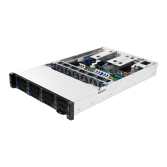
Page 9: Internal Features
RM237-C622LM 2.2 Internal Features... - Page 10 From LAN Mezzanine Card Slot Riser Card Assembly 1 Storage Mezzaine Card Slot Riser Card Assembly 2 Riser Card Assembly 3 2 x Power Supply Units 2 x 2.5" SATA 3(6Gb/s) / 2.5" SAS (12Gb/s) HDD (Hot-swapable) 2.5" HDD Backplane Board (BPB) Serverboard System Fan 1 (Hot-swapable) System Fan 2 (Hot-swapable)
-
Page 11: System Front Panel
RM237-C622LM 2.3 System Front Panel Description Front Control Panel 1 x USB 2.0 Port 12 x 2.5" or 3.5" SATA 3(6Gb/s)/ SAS (12Gb/s) HDDs 1 x USB 3.0 Port 1 x VGA Port... -
Page 12: System Rear Panel
2.4 System Rear Panel HDD1 HDD0 Redundant PSU 1+1: Only one PSU is allowed to be removed while the server is running. Description 2 x 2.5" SATA 3(6Gb/s)/ 2.5" SAS (12Gb/s) HDDs Add-on PCIE Card Slots (on Riser Card Assembly) Add-on PCIE Card Slots (on Riser Card Assembly) I/O Shield (depends on the specification of the server board) Add-on PCIE Card Slots (on Riser Card Assembly) -
Page 13: Front Control Panel Buttons And Leds
RM237-C622LM 2.5 Front Control Panel Buttons and LEDs Front Control Panel Description Power Button and LED UID Button and LED System Reset Button HDD Activity LED System Event LED LAN1, LAN2 Activity LEDs USB 2.0 Port VGA Port USB 3.0 Port *Please be noted that the functions are supported depending on the type of the server board. - Page 14 System Reset Button When the system is completely unresponsive, press the system reset button to reboot the server without shutting it off and initialize the system. Status LED Definitions Power LED Status Description Green Power on Power off ID LED Status Description Blue...
-
Page 15: Psu Led
RM237-C622LM 2.6 PSU LED PSU LED PSU Status LED Status Description Green Normal work; output ON and OK Amber Module fault/protection in operating mode (failure, OCP, OVP, Fan Fail, OTP, UVP) AC cord unplugged Amber blinking at 0.5Hz Warning (high temp, high power, high current, slow fan) Green blinking at 0.5Hz... -
Page 16: Chapter 3 Hardware Installation And Maintenance
Chapter 3 Hardware Installation and Maintenance This chapter helps you assemble the chassis and install components. Before You Begin Before you work with the server, pay close attention to the “Important Safety Instructions” at the beginning of this manual. 1. Make sure the server is powered off. Power down the server if it is still running. -
Page 17: Server Top Cover
RM237-C622LM 3.1 Server Top Cover Removing the Server Top Cover 1. Before removing the top cover, power off the server and unplug the power cord. 2. The system must be operated with all the chassis top cover installed to ensure proper cooling. - Page 18 Installing the Server Top Covers 1. Lower the top cover on the chassis , with the latch handle open. 2. Make sure the side latches align with the cutouts. Push the cover toward the front side of the chassis. 3. Close the latch handle.
-
Page 19: Hard Drive
RM237-C622LM 3.2 Hard Drive 3.2.1 Installing a Hard Disk Drive into 2.5" Hard Drive Tray The chassis supports hot-swappable 2.5" hard drives. Removing 2.5” Hard Drive Trays from the Chassis 1. Press the locking lever latch on the drive tray to unlock the retention lever. - Page 20 Installing a 2.5” Hard Drive to the Hard Drive Tray 1. Engage two embossed pins into the side dimples on the tray. 2. Carefully push down the other side of the tray until the other two embossed pins and side dimplws lock into place.
- Page 21 RM237-C622LM 3.2.2 Installing a Hard Disk Drive into 3.5" Hard Drive Tray The chassis supports hot-swappable 3.5" hard drives. Removing 3.5” Hard Drive Trays from the Chassis 1. Press the locking lever latch on the drive tray to unlock the retention lever.
- Page 22 Installing a 3.5” Hard Drive to the Hard Drive Tray 1. Engage two embossed pins into the side dimples on the tray. 2. Carefully push down the other side of the tray until the other two embossed pins and side dimplws lock into place.
- Page 23 RM237-C622LM Installing a 2.5” Hard Drive to the 3.5” Hard Drive Tray 1. Place a 2.5" HDD into the tray with the printed circuit board side facing down. Carefully align the mounting holes in the hard drive and the tray.
-
Page 24: Power Supply
3.3 Power Supply Installing and Removing the Power Supply Before replacing the power supply, power off the server, unplug the power cord, and discon- nect all wiring from the power supply. Installing the Power Supply Unit The system can accommodate four AC or two DC power supplies in the bay at the rear of the chassis. -
Page 25: Add-On Card
RM237-C622LM 3.4 Add-on Card 1. You can install an add-on card to the chassis with the riser card assembly installed on the serverboard. 2. Before installing the add-on card, power off the server and unplug the power cord. Please be noted that add-on card is supported for certain models only. Please check the rear panel of your chassis and see if a PCI Express slot is provided on the I/O shield. - Page 26 2. Remove the screw securing the slot cover to the assmebly. 3. Slide the slot cover out sideways. 4. Install an add-on card into to the riser-card assembly. 5. Tighten the screw to secure the add-on card.
- Page 27 RM237-C622LM 6. Install the add-on card assembly to the chassis. Align the plate of the add-on card with the openings in the back of the chassis. 7. User screws to secure the add-on card assembly to the chassis.
-
Page 28: Mezzanine Card Support List
Appendix A Mezzanine Card Support List This motherboard supports the following ASRock Rack mezzanine cards. Mezz Card Type Mezz Slot Type Model LAN Card Mezz Type A M350 LAN Card Mezz Type A M350R LAN Card Mezz Type A M540... -
Page 29: Installing The Cpu And Heatsink
RM237-C622LM Appendix B Installing the CPU and Heatsink 1. Before you insert the CPU into the socket, please check if the PnP cap is on the socket, if the CPU surface is unclean, or if there are any bent pins in the socket. Do not force to insert the CPU into the socket if above situation is found. - Page 30 1. Before you installed the heatsink, you need to spray thermal interface material between the CPU and the heatsink to improve heat dissipation. 2. Illustration in this documentation are examples only. Heatsink or fan cooler type may differ.
- Page 31 RM237-C622LM...
- Page 32 Tighten the two Corner Plunger to 12 IN.LB. Two turns at a time. Tighten the two Middle Nuts to 12 IN.LB. Two turns at a time.
-
Page 33: Installation Of Memory Modules (Dimm)
RM237-C622LM Appendix C Installation of Memory Modules (DIMM)
Need help?
Do you have a question about the RM237-C622LM and is the answer not in the manual?
Questions and answers