Rinstrum R320 Reference Manual
Hide thumbs
Also See for R320:
- Reference manual (85 pages) ,
- Communications manual (49 pages) ,
- Quick start manual (32 pages)
Table of Contents
Advertisement
Reference Manual V1.00
1.
INTRODUCTION ................................................................................................................... 5
1.1.
Overview .................................................................................................................... 5
1.2.
Approvals ................................................................................................................... 5
1.2.1.
1.3.
The Manuals Set ........................................................................................................ 6
1.4.
This Reference Manual .............................................................................................. 6
1.5.
Document Conventions .............................................................................................. 6
2.
SPECIFICATIONS ................................................................................................................. 7
3.
INSTALLATION .................................................................................................................... 8
3.1.
Introduction ................................................................................................................ 8
3.2.
General Warnings ...................................................................................................... 8
3.3.
Electrical Safety ......................................................................................................... 8
3.4.
Cleaning ..................................................................................................................... 8
3.5.
Panel Mount Template ............................................................................................... 8
3.6.
Cable Connections ..................................................................................................... 9
3.7.
DC Power (DC PWR + , DC PWR -) ......................................................................... 9
3.8.
Load Cell Connection ................................................................................................. 9
3.8.1.
3.8.2.
3.8.3.
3.9.
Auxiliary Connections ............................................................................................... 11
3.9.1.
3.9.2.
3.9.3.
3.10. opto-LINK (Optional) ................................................................................................ 16
3.11. Connecting Shields .................................................................................................. 17
3.11.1.
3.12. Regulatory Sealing Requirements ............................................................................ 17
4.
DATA ENTRY ...................................................................................................................... 18
4.1.
Editing Annunciators ................................................................................................ 18
4.2.
Numeric Entry .......................................................................................................... 19
4.3.
Selections and Options ............................................................................................ 19
5.
BASIC OPERATION ........................................................................................................... 20
5.1.
Display ..................................................................................................................... 20
5.2.
Has a key been locked? ........................................................................................... 21
5.3.
Editing Function ....................................................................................................... 21
5.4.
5.5.
POWER Key ............................................................................................................ 21
003R-677-210
Table of Contents
Trade versions ........................................................................................... 6
Load Cell Signals and Scale Build .............................................................. 9
4-Wire Connection ................................................................................... 10
6-Wire Connection ................................................................................... 10
RS-232 Serial ........................................................................................... 11
Remote Input ........................................................................................... 14
Outputs .................................................................................................... 15
Cable Shield Connection and Earthing ..................................................... 17
Software Versions 3.xx
Page 1
Advertisement
Table of Contents

Related Manuals for Rinstrum R320


Summary of Contents for Rinstrum R320
-
Page 1: Table Of Contents
Reference Manual V1.00 Software Versions 3.xx Table of Contents INTRODUCTION ........................5 1.1. Overview ........................5 1.2. Approvals ........................5 1.2.1. Trade versions ................... 6 1.3. The Manuals Set ......................6 1.4. This Reference Manual ....................6 1.5. Document Conventions ....................6 SPECIFICATIONS ......................... - Page 2 Reference Manual V1.00 Software Versions 3.xx 5.6. ZERO Key ........................ 22 5.7. TARE Key ........................ 22 5.8. GROSS/NET Key ..................... 23 5.9. PRINT Key ....................... 23 5.10. FUNCTION Key ....................... 23 CONFIGURATION ......................24 6.1. General Setup Information ..................24 6.2.
- Page 3 Reference Manual V1.00 Software Versions 3.xx 9.2. NET - Network Communications ................40 9.3. Auto Weight Format String ..................40 9.4. Menu Setup - SERIAL (Serial Communications Options) ......... 41 STANDARD PRINTING – K344 (NO CLOCK/CALENDAR) ..........43 STANDARD PRINTING – K35* (WITH CLOCK/CALENDAR) ..........44 11.1.
- Page 4 Reference Manual V1.00 Software Versions 3.xx APPENDIX - TRADE SEALING DETAILS ................54 APPENDIX – ABS R320 DIMENSIONS ................55 APPENDIX – STAINLESS STEEL R323 DIMENSIONS ............. 57 SETUP MENU QUICK REFERENCE .................. 59 ERROR MESSAGES ......................61 19.1. Weighing Errors ....................... 61 19.2.
-
Page 5: Introduction
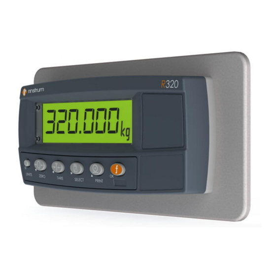
Reference Manual V1.00 Software Versions 3.xx 1. Introduction This instrument is a precision digital indicator using the latest Sigma-Delta analogue to digital conversion technology to ensure fast and accurate weight readings. Figure 1: Weight Indicator The setup and calibration of the instrument are digital, with a non-volatile security store for all setup parameters. -
Page 6: Trade Versions
This manual contains details of information common to all derivatives of the R320 series of indicators. Note: In this manual any reference to the R320 includes the other indicators in the series except where stated otherwise. 1.5. Document Conventions The following document conventions (typographical) are used throughout this Reference Manual. -
Page 7: Specifications
Reference Manual V1.00 Software Versions 3.xx 2. Specifications R320 (ABS Housing) R323 (Stainless Steel) Resolution Up to 60,000 divisions, minimum of 0.25µV/division Zero Cancellation ± 2.0mV/V Span Adjustment 0.1mV/V to 3.0mV/V full scale 5 V for up to 4 x 350 or 8 x 700 ohm load cells (4-wire or 6-wire plus shield) Excitation Max total load cell resistance: 3,500Ω... -
Page 8: Installation
Reference Manual V1.00 Software Versions 3.xx Installation 3.1. Introduction The following steps are required to set up the indicator. • Inspect indicator to ensure good condition. • Use connection diagrams to wire up load cell, power and auxiliary cables as required. •... -
Page 9: Cable Connections
Reference Manual V1.00 Software Versions 3.xx 3.6. Cable Connections All cable connections are made to the rear of the instrument using screwless terminals. Wires must be stripped of insulation by at least 10mm. To install, depress the orange lever beside the terminal required and push wire into the hole. Release the lever and pull gently on the wire to ensure it is securely trapped in the terminal. -
Page 10: 4-Wire Connection
Reference Manual V1.00 Software Versions 3.xx 3.8.2. 4-Wire Connection The minimum connectivity requirements are the connection of four wires (ie. Excitation + and – along with Signal + and –). Internally the instrument has a precision analogue switch that connects the Sense + and – lines directly to the Excitation + and – lines when 4-wire mode is selected. -
Page 11: Auxiliary Connections
Reference Manual V1.00 Software Versions 3.xx 3.9. Auxiliary Connections This section provides diagrams to illustrate the terminal connections. 3.9.1. RS-232 Serial Network: One Instrument to PC (RXD, TXD, GND) Figure 5: RS-232 – One Instrument to PC using COM Port (DB9) Figure 6: RS-232 –... - Page 12 Reference Manual V1.00 Software Versions 3.xx Ring Networks: Multiple Instruments to PC (RXD, TXD, GND) Instruments can be configured in a Ring Network. The Short Ring Network layout can be used in situations up to a total cable run length of about 150 m (500 ft) at 9600 baud in a clean EMC environment.
- Page 13 Reference Manual V1.00 Software Versions 3.xx Long Ring Network: Multiple Instruments to PC (RXD, TXD, GND) The Long Ring Network layout can be used in situations where each leg of the cable run can be up to about 150 m (500 ft) at 9600 baud. If there are communications errors, lower the baud rate to 4800 or 2400.
-
Page 14: Remote Input
Reference Manual V1.00 Software Versions 3.xx Printer Connections (RXD/TXD, GND and DTR) Figure 9: RS-232 – Instrument to Printer (DB25) Remote Display (TXD, GND) The remote display documentation should be referred to for connection details. Connect TXD to RXD and GND to GND on the remote display. 3.9.2. -
Page 15: Outputs
Reference Manual V1.00 Software Versions 3.xx 3.9.3. Outputs The output drivers for the instrument are isolated open emitter transistor drives that are capable of driving up to a total of 300mA. This configuration allows for the direct connection of the instrument outputs to most types of PLC. The voltage applied to the COM terminal appears on the output lines (ie. -
Page 16: Opto-Link (Optional)
Reference Manual V1.00 Software Versions 3.xx 3.10. opto-LINK (Optional) A temporary infrared communications link can be established between the instrument and a PC using an optional opto-LINK cable. The optional opto-LINK cable can be used to transfer setup and calibration information from a PC (eg. to be stored for later use and/or transferred to other instruments). -
Page 17: Connecting Shields
Reference Manual V1.00 Software Versions 3.xx 3.11. Connecting Shields To obtain full EMC or for RFI immunity, cable shields MUST be connected to the earth lug on the rear of the instrument. Figure 14 illustrates an example of possible connections. Also shown are the connecting cables restrained using cable ties fastened around the cable strain relief anchors. -
Page 18: Data Entry
Reference Manual V1.00 Software Versions 3.xx Data Entry Throughout the setup and normal weighing mode, different data entry methods are used. Each method is described below. When using the keypad for normal operation, press the key on keypad to initiate the feature. 4.1. -
Page 19: Numeric Entry
Reference Manual V1.00 Software Versions 3.xx 4.2. Numeric Entry A numeric entry box allows the input of a number. When entering a number, the display will show digits with the currently selected digit flashing. The <SEL> key is pressed to select a digit to change. -
Page 20: Basic Operation
Reference Manual V1.00 Software Versions 3.xx Basic Operation Figure 16: Display and Controls Illustration 5.1. Display Weight The Weight Display indicates the weight readings, setup information, errors and warnings. Display Units The Units Display shows the units of the weight reading as: grams (g), kilograms (kg), pounds (lb), tonnes (t) or none. -
Page 21: Has A Key Been Locked
Reference Manual V1.00 Software Versions 3.xx 5.2. Has a key been locked? A single press of each key triggers the weighing operation printed on it. The instrument allows individual keys to be disabled in the setup. All keys are enabled at the factory, but some keys may have been intentionally disabled (locked) during installation. -
Page 22: Zero Key
Reference Manual V1.00 Software Versions 3.xx 5.6. ZERO Key When an empty scale has drifted away from a true zero reading, this key is used to perform a zero adjustment on the scale display. The zero adjustment is stored when power is removed and is re-used when next powered up. -
Page 23: Gross/Net Key
Reference Manual V1.00 Software Versions 3.xx 5.8. GROSS/NET Key This key toggles the weight display between the Gross weight and the Net weight (provided that a Tare has previously been acquired using the <TARE> key). opto-LINK This feature is used to temporarily connect a PC to the instrument for calibration Activation and setup purposes. -
Page 24: Configuration
Reference Manual V1.00 Software Versions 3.xx Configuration 6.1. General Setup Information Configuration and calibration can be performed entirely from the front panel, using the digital setup facility. When Full Setup is used, all menu items are accessible and care must be taken to ensure no accidental changes are made to calibration and trade settings. -
Page 25: Filtering Techniques
Reference Manual V1.00 Software Versions 3.xx Signal voltages can be calculated as follows: Calculating the full scale signal (load cell): Since the instrument uses 5V load cell excitation, the absolute signal voltage is: Calculating the signal resolution: 6.3. Filtering Techniques There is a trade off between noise filtering and the step-response time of the system. -
Page 26: Passcodes
Reference Manual V1.00 Software Versions 3.xx instrument is powered up, or setup mode is entered/exited, the current value in the counter(s) is displayed briefly (eg. C00010). Industrial OIML NTEP The Calibration Counter The Calibration Counter The Calibration Counter increments when trade increments when trade increments when trade critical critical settings, marked... - Page 27 Reference Manual V1.00 Software Versions 3.xx Full/Safe setup. Should this occur the ENTER PASS prompt will not display, but instead the ENTRY DENIED message displays and returns the user to the normal operating mode. To rectify this issue the instrument must be turned off. When the instrument is turned back on the passcode counter is reset to zero (allowing the user to enter the correct passcode).
-
Page 28: Calibration
Reference Manual V1.00 Software Versions 3.xx Calibration The calibration of the indicator is fully digital. The calibration results are stored in permanent memory for use each time the instrument is powered up. Note: Some of the digital setup steps can affect calibration. The BUILD and OPTION settings MUST be configured before calibration is attempted. -
Page 29: Zero (Zero Calibration Routine)
Reference Manual V1.00 Software Versions 3.xx 7.1.1. ZERO (Zero Calibration Routine) Press the <SEL> key to start. The display will show the current weight. Remove all weight from the scale structure. Press <SEL>, <EDT> or <OK> to execute a Zero Calibration. The display will show Z.in.P to indicate that zeroing is in progress. -
Page 30: Setup
Reference Manual V1.00 Software Versions 3.xx Setup The instrument digital setup facilities provide the means to configure and calibrate the instrument. 8.1. Accessing Setup There are two methods to access the Setup area. For further details of menu items available in each setup mode, refer to the Setup Menu Quick Reference page 59. -
Page 31: Setup Display Prompts
Reference Manual V1.00 Software Versions 3.xx 8.1.3. Setup Display Prompts When accessing Full or Safe Setup the instrument will beep twice and then display the following: • FULL or SAFE (depending on setup access type) • SETUP • Software Version (eg. V1.0) •... -
Page 32: Setup Menus
Reference Manual V1.00 Software Versions 3.xx 8.4. Setup Menus 8.4.1. BUILD (Scale Build) Settings within this Group are used to configure the indicator to suit the current application. It is important to fully set the options within this group before calibration is attempted. Later changes to items within this group may invalidate the current calibration data. -
Page 33: Option (Scale Options)
Reference Manual V1.00 Software Versions 3.xx 8.4.2. OPTION (Scale Options) Items within this Group are used to configure the operating parameters of the scale. This is where the basic use of the scale is set. This setting configures the instrument for Industrial, OIML, or NTEP operation. -
Page 34: Cal (Scale Calibration)
Reference Manual V1.00 Software Versions 3.xx to Full Setup) Options are: OFF, ON Default: OFF 8.4.3. CAL (Scale Calibration) Items within this group perform various calibration routines. Certain items in the Scale Build can affect the calibration of the scale. Always check that these sections are correctly configured to suit the current application before attempting to calibrate the scale. - Page 35 Reference Manual V1.00 Software Versions 3.xx access. Refer to Passcodes page 26 and Accessing Setup page 30 for more Digital Setup) information. Range 000000 to 999999 Default: 000000 It is important to note that when restricting Full access to Setup the passcode must not be forgotten.
- Page 36 Reference Manual V1.00 Software Versions 3.xx REM.FN This item allows the indicator to be triggered from a remote input (see section 3.9.2 Remote Input). The remote input can be set to have: (Remote Function) - no function (ie. NONE) or K344, K35* - it can be set to mimic one of the front five panel key functions (ie.
-
Page 37: Cloc (Clock) - K35
Reference Manual V1.00 Software Versions 3.xx Refer to Menu Setup - SERIAL (Serial Communications Options) Page 41 and Setpoint Menu Setup - SET.PTS page 48. 8.4.5. CLOC (Clock) – K35* CLOCK (Clock Settings) Items within this group set date and time related functions. Available This sets the date format. -
Page 38: Factry (Factory Adjustment Menu)
Reference Manual V1.00 Software Versions 3.xx 8.4.7. FACTRY (Factory Adjustment Menu) Clears the A/D conversion overload counter. The instrument will prompt with Cont. N. Press <EDT> to change to Cont. Y and <OK> to continue. When Cont. Y has been chosen the instrument will display DONE to indicate that the operation has been completed.FACTRY (Factory Adjustment Menu) Restores all settings in the digital setup, which are not calibration... -
Page 39: Serial Outputs (K344, K35*)
Reference Manual V1.00 Software Versions 3.xx Serial Outputs (K344, K35*) The instrument supports a bi-directional RS-232 output and temporary opto-LINK connection, allowing for a number of serial output types for communications with external devices such as printers, computers, PLCs or remote displays. Refer to opto-LINK Activation page 16. -
Page 40: Net - Network Communications
Reference Manual V1.00 Software Versions 3.xx 9.2. NET - Network Communications NET Protocol The NET network communications feature is normally used to control indicators remotely from a central computer, or PLC. A NET command and response might be: 20110150:<CR><LF> 9F110150:07/01/2030 17:29<CR><LF> Ring Network Instruments can be installed in a Ring Network. -
Page 41: Menu Setup - Serial (Serial Communications Options)
Reference Manual V1.00 Software Versions 3.xx • S1: Displays G/N/U/O/E representing Gross / Net / Underload / Overload / Error, respectively. • S2: Displays M/^ representing Motion / Stable, respectively. • S3: Displays Z/^ representing centre of Zero / Non-Zero, respectively. •... - Page 42 Reference Manual V1.00 Software Versions 3.xx • N or O or E: Parity bit: (N) None, (O) Odd, (E) Even • 8, 7: Number of data bits • 1, 2: Number of stop bits • -, D: DTR handshake disabled or enabled •...
-
Page 43: Standard Printing - K344 (No Clock/Calendar)
Reference Manual V1.00 Software Versions 3.xx Standard Printing – K344 (No Clock/Calendar) K344 and K346 use a standard print format that includes support for printing number of pieces and samples pieces if counting is being used. Should custom printing, totalising or date and time be required, the unit can be upgraded to firmware in the K35* range. -
Page 44: Standard Printing - K35* (With Clock/Calendar)
Reference Manual V1.00 Software Versions 3.xx Standard Printing – K35* (with Clock/Calendar) The K35* range of firmware includes a standard print format and programmable printing. The standard print format incorporates number of pieces and totals if counting is being used. When the instrument has Print or Automatic print enabled, the standard print format will be used or if configured, the custom print format will be used. -
Page 45: Printing Total Weight
Reference Manual V1.00 Software Versions 3.xx 11.2. Printing Total Weight In addition to the printout, the instrument adds the weight and pieces printed to the internal weight and count totals. Example print format after a series of prints followed by a long press of <PRINT> key that prints totals. -
Page 46: Programmable Printing - K35
Reference Manual V1.00 Software Versions 3.xx Programmable Printing – K35* Two user determined print strings with tokens can be programmed into an instrument using View300. 12.1. How to set custom print strings using View 300 - Connect instrument to PC with View300 - Open full session - select instrument menu/ select custom print format. -
Page 47: Printing Custom Print Strings
Reference Manual V1.00 Software Versions 3.xx 12.5. Printing Custom Print Strings Short Press <PRINT> key: to print the programmed print string up to 80 characters including tokens. Long Press <PRINT> key: to print the programmed summary print string up to 20 characters including tokens. -
Page 48: Setpoints - K356
Reference Manual V1.00 Software Versions 3.xx Setpoints – K356 The instrument is capable of working with two internal setpoints. The status of these setpoints is displayed on the LCD. Each setpoint is associated with a physical output driver but it may also be simply used as an indicator. -
Page 49: Setpoint Configuration
Reference Manual V1.00 Software Versions 3.xx value and turned off otherwise. UNDER: The output is turned on when the source weight is under the target value and turned off otherwise. MOTION: The output will be driven when ever weight motion is detected. ZERO: The output will be driven whenever the weight motion is within the “zero”... -
Page 50: Setpoint Type (Over/Under) And Hysteresis
Reference Manual V1.00 Software Versions 3.xx 13.5. Setpoint Type (OVER/UNDER) and Hysteresis Hysteresis defines the amount of weight required for an active setpoint to become inactive again. For an OVER setpoint it will be the amount the weight must fall below the target to turn off. For an UNDER setpoint it will be the amount of weight that it goes over the target by for the (already active) output to turn off. -
Page 51: Special Functions Key - K35
Reference Manual V1.00 Software Versions 3.xx Special Functions Key – K35* 14.1. Introduction The K35* firmware allows for the <FUNCTION> key to be configured to a range of special functions. As the K356 firmware allows for setpoints, there is an additional special function available where the key can be used to gain access to the setpoint threshold values. -
Page 52: Hold And Peak Hold
Reference Manual V1.00 Software Versions 3.xx 14.2.5. HOLD and PEAK HOLD The <HOLD> key implements a manual Hold function. The <PEAK> key implements a Peak Hold function where the largest absolute weight, either positive or negative is stored in the peak value (eg. -
Page 53: Set.pt (K356)
Reference Manual V1.00 Software Versions 3.xx Press and hold the <A.TARE> key to set the threshold above which the automatic tare occurs. Press the <OK> key to enter the automatic tare threshold. Change the threshold to the required value using the <SEL> and <EDT> keys. Press the <OK>... -
Page 54: Appendix - Trade Sealing Details
Reference Manual V1.00 Software Versions 3.xx Appendix - Trade Sealing Details Affix sealing stickers to the rear of the instrument, over one or more screws in the locations indicated. Also affix a sealing sticker over the load cell cable where the cable-tie strain relief is attached, as indicated. Affix stickers in the locations indicated. -
Page 55: Appendix - Abs R320 Dimensions
Reference Manual V1.00 Software Versions 3.xx Appendix – ABS R320 Dimensions Weight Indicator Dimensions in mm (1 inch = 25.4 mm) 3D View Front View Side View Back View Weight Indicator (Desk Mount with Battery Compartment) Dimensions in mm (1 inch = 25.4 mm) - Page 56 Reference Manual V1.00 Software Versions 3.xx Weight Indicator (IP65 rear boot) Dimensions in mm (1 inch = 25.4 mm) 3D View Front View Side View Back View Bottom View Page 56 003R-677-210...
-
Page 57: Appendix - Stainless Steel R323 Dimensions
Reference Manual V1.00 Software Versions 3.xx Appendix – Stainless Steel R323 Dimensions Weight Indicator (Desk Mounted) Dimensions in mm (1 inch = 25.4 mm) Desk Mounted 3D View Front View Side View Bottom View Weight Indicator (Panel Mounted) Dimensions in mm (1 inch = 25.4 mm) Panel Mounted 3D View Front View Rear View... - Page 58 Reference Manual V1.00 Software Versions 3.xx Weight Indicator (Wall Mounted) Dimensions in mm (1 inch = 25.4 mm) Wall Mounted 3D View Front View Side View Back View Page 58 003R-677-210...
-
Page 59: Setup Menu Quick Reference
Reference Manual V1.00 Software Versions 3.xx Setup Menu Quick Reference Note: ⊗ Available only in Full Setup. Changing this setting will increment the Calibration Counter. 1 Available only in Full Setup. Changing this setting will not increment the Calibration Counter. ⊗... - Page 60 Reference Manual V1.00 Software Versions 3.xx (Key Functions) AUT.OFF (Auto Power Off / Battery Operation) B.LIGHT (Backlight Operation) REM.FN (Remote Function) REM.CHR (Remote Input Transmit Idle Character) BAT.VLT (Battery Voltage) PWR.FN (Power Function) TYPE (Serial Output Type) SERIAL FORMAT (Serial Output Format) BAUD (Serial Baud Rate) BITS (Serial Format Options) ADDRES (Instrument Address)
-
Page 61: Error Messages
Reference Manual V1.00 Software Versions 3.xx Error Messages A number of error messages may be displayed to warn of operation outside of the acceptable limits. These messages are described below. Short messages (XXXXX) will appear as a single message on the display. Longer messages (XXXXX) (YYYYY) will appear on the display in two parts, first the (XXXXX) part, then the (YYYYY) part. -
Page 62: Setup And Calibration Errors
Reference Manual V1.00 Software Versions 3.xx 19.2. Setup and Calibration Errors These messages show status messages or errors that may occur during the instrument setup and calibration. Error Description Resolution (ENTRY) The instrument may be in Safe Setup Access Full Setup to edit the item. and an item that needs Full Setup has (DENIED) been selected for editing. -
Page 63: Diagnostic Errors
Reference Manual V1.00 Software Versions 3.xx 19.3. Diagnostic Errors The instrument continually monitors the condition of the internal circuits. Any faults or out-of- tolerance conditions are shown on the display as an E type error message. In the table below the following terms are used: - Check: This item can be checked on site by service personnel. -
Page 64: Appendix - Rinwire Protocol
Reference Manual V1.00 Software Versions 3.xx Appendix - rinWIRE Protocol The protocol uses ASCII characters with a single master POLL / RESPONSE message structure. All information and services are provided by registers each of which has its own register address. Basic Message Format The basic message format is as follows: ADDR... - Page 65 Reference Manual V1.00 Software Versions 3.xx CMD is a two character hexadecimal field: Command Description Read Literal Read register contents in a ‘human readable’ format Read Final Read register contents in a hexadecimal data format Write Final Write the DATA field to the register. Execute Execute function defined by the register using parameters supplied in the DATA field.
- Page 66 Reference Manual V1.00 Software Versions 3.xx :DATA carries the required information for the message ‘:’ (COLON) character is used to separate the header (ADDR CMD REG) and DATA information. DATA Carries the information for the message. Some messages require no DATA (eg Read Commands) so the field is optional.
-
Page 67: Glossary Terms
Reference Manual V1.00 Software Versions 3.xx Glossary Terms Term Definition The communications protocol used to communicate with the R300 Series COMM Count-by The smallest change in weight units that the display can show. See also Resolution. Division A single graduation. EEPROM Electrically Erasable Programmable Read-Only Memory Electro-Magnetic Compatibility Regulation... -
Page 68: List Of Tables
Reference Manual V1.00 Software Versions 3.xx Figure 9: RS-232 – Instrument to Printer (DB25) ................14 Figure 10: Remote Input ....................... 14 Figure 11: Instrument Outputs to Drive Relay ................15 Figure 12: Instrument Outputs to Drive PLC ................. 15 Figure 13: opto-LINK Attachment .................... -
Page 69: Index
Reference Manual V1.00 Software Versions 3.xx Index Direct mV/V opto-LINK Printing Calibration, 29 Activation, 22, Counting Sample, 4-Wire Connection, 10 Direct Span Calibration, 29 Group and Items, 31 Gross or Net, 43, 6-Wire Connection, 10 Direct Zero Calibration, 29 HI.RES, 32, 59 Document ADDRES, 42, 60 HOLD, 52... - Page 70 Reference Manual V1.00 Software Versions 3.xx Sigma-Delta A/D Units Display, 20 Z.in P, 29, 34 converter, 5 USE, 25, 33, 59 Z.RANGE, 22, 33, 59 TARE Key, 22 SPAN, 34, 59 Z.TRAC, 33, 59 TARG.HI, 48, 49, 60 Span Calibration ZERO, 34, 59 TEST, 51 Weighing Errors, 61...
Need help?
Do you have a question about the R320 and is the answer not in the manual?
Questions and answers