Table of Contents
Advertisement
Quick Links
Advertisement
Table of Contents

Related Manuals for Ross DAC-9516


Summary of Contents for Ross DAC-9516
- Page 1 DAC-9516 User Guide...
- Page 2 Ross has become well known for the Ross Video Code of Ethics. It guides our interactions and empowers our employees. I hope you enjoy reading it below. If anything at all with your Ross experience does not live up to your expectations be sure to reach out to us at solutions@rossvideo.com.
-
Page 3: Safety Notices
Copyright ©2018 Ross Video Limited, Ross®, and any related marks are trademarks or registered trademarks of Ross Video Limited. All other trademarks are the property of their respective companies. PATENTS ISSUED and PENDING. All rights reserved. No part of this publication may be reproduced, stored in a retrieval system, or transmitted in any form or by any means, mechanical, photocopying, recording or otherwise, without the prior written permission of Ross Video. -
Page 4: Environmental Information
To avoid the potential release of those substances into the environment and to diminish the need for the extraction of natural resources, Ross Video encourages you to use the appropriate take-back systems. These systems will reuse or recycle most of the materials from your end-of-life equipment in an environmentally friendly and health conscious manner. - Page 5 Company Address Ross Video Limited Ross Video Incorporated 8 John Street P.O. Box 880 Iroquois, Ontario Ogdensburg, New York Canada, K0E 1K0 USA 13669-0880 General Business Office: (+1) 613 4886 Fax: (+1) 613 4425 ...
-
Page 7: Documentation Conventions
IP Address, Subnet Mask, and Gateway for your DAC-9516. Contacting Technical Support At Ross Video, we take pride in the quality of our products, but if problems occur, help is as close as the nearest telephone. - Page 8 This team of highly trained staff is available to react to any problem and to do whatever is necessary to ensure customer satisfaction. • Technical Support: (+1) 613-652-4886 • After Hours Emergency: (+1) 613-349-0006 • E-mail: techsupport@rossvideo.com • Website: http://www.rossvideo.com 8 • Introduction DAC-9516 User Guide (v3.0)
-
Page 9: Before You Begin
32, 44.1, or 48kHz sample rates, and provides two copies of stereo (A, B) balanced analog audio. The DAC-9516 provides reclocking of the AES stream as well as a state of the art 128X over-sampled Delta Sigma Modulator DAC to convert to analog audio. Following the D-A conversion, the analog audio passes through a very high quality reconstruction filter, which assures low distortion and noise. - Page 10 Features Some features of the DAC-9516 include: • Supports data rates in the 28kHz to 50kHz range including 32kHz, 44.1kHz, and 48kHz • 24bit DAC resolution • Reclocking to reduce jitter and noise • Conformity to AES-3id 1995 and SMPTE 276M •...
-
Page 11: Hardware Overview
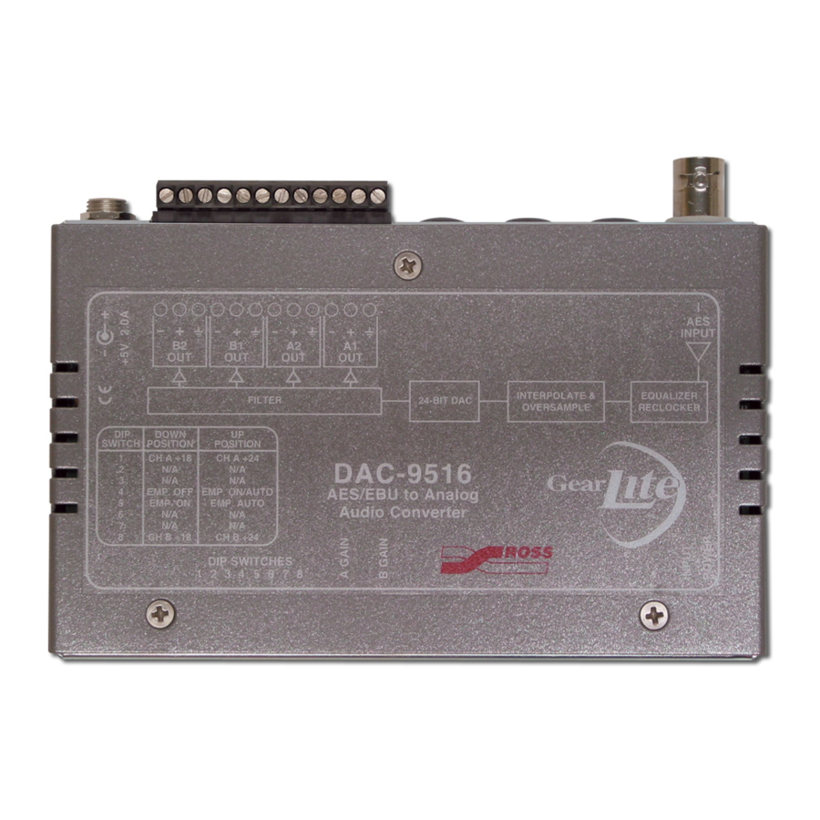
The chassis faceplate of the DAC-9516 provides a silk-screen map of the connections available. Figure 3.1 illustrates the DAC-9516 faceplate label. The chassis of the DAC-9516 also includes status LEDs that display the status of power, and AES input. INPUT INTERPOLATE &... -
Page 12: Analog Output Connections
Status Description Green When this LED is continually lit green, power is supplied to the DAC-9516 When unlit, this LED indicates a loss of power. Analog Output Connections Two balanced analog audio output channels (positive, negative, and ground terminals for each channel) are provided on a 12-pin terminal block. -
Page 13: Physical Installation
Physical Installation If you have questions pertaining to the installation of DAC-9516, please contact us at the numbers listed in the section “Contacting Technical Support” on page 7. Our technical staff is always available for consultation, training, or service. For More Information on... - Page 14 Use the flat metal plate for permanent mounting to a rack, a desk, or any other location where bolts or screws can be applied. Be sure to position the module to allow for operator adjustments, if required. Mounting screws are not provided by Ross Video. To install the Flat Metal Plate Remove the 2 screws from the bottom of the chassis.
-
Page 15: Optional Mounting Accessories
Optional Mounting Accessories Ross Video is committed to providing practical solutions for the needs of your high-quality broadcast facility. The following products may be ordered separately to expand your installation options. - Page 16 16 • Physical Installation DAC-9516 User Guide (v3.0)
-
Page 17: Analog Audio Cabling
The DAC-9516 can accommodate any full-scale digital (FSD) level in the -12dBFS to -30dBFS range. Connect the AES/EBU input cable to the DAC-9516 according to the designation indicated on the chassis label. (Figure 5.1) The input is internally terminated at 75ohms. - Page 18 OUT A2 Figure 5.2 DAC-9516 — ANLG Audio Connections Verify the silk-screen on the DAC-9516 chassis and Figure 5.2 to locate the pins for each input (A, B). Insert an analog audio wire into the designated polarity slot on the block.
-
Page 19: Using The Dip Switches
The DIP Switches on the bottom of the DAC-9516 enable you to further setup your module. Using the DIP Switches The top of the DAC-9516 chassis includes a label that provides a condensed DIP switch settings chart. This chart is intended as a quick reference guide. Refer to for DIP Switch locations. - Page 20 B channel (Left and Right). A GAIN B GAIN Figure 6.2 DAC-9516 — Potentiometer Locations To adjust the output level Select the approximate FSD level (18dB or 24dB) using the headroom DIP switches (A Level and B Level). Turn the potentiometers (A Gain and B Gain) to trim the FSD level (± 6dB) to your installation’s standard.
-
Page 21: Audio Levels
This means that for a -20dBFS input, the analog outputs may be set to -8dBu to +10dBu. Likewise, for a -18dBFS input, the output may be set anywhere in the range of -6dBu to +12dBu. Keep in mind that the maximum output level (1% THD+N) is 27dBu (@ 1kHz). DAC-9516 User Guide (v3.0) Setup • 21... - Page 22 22 • Setup DAC-9516 User Guide (v3.0)
-
Page 23: Warranty And Repair
Should you find that this DAC-9516 has failed after your warranty period has expired, we will repair your defective product should suitable replacement components be available. You, the owner, will bear any labor and/or part costs incurred in the repair or refurbishment of said equipment beyond the THREE (3) year warranty period. - Page 24 24 • Warranty and Repair DAC-9516 User Guide (v3.0)
-
Page 25: Technical Specifications
Technical Specifications This chapter provides technical information for DAC-9516. Specifications are subject to change without notice. Analog Audio Output Table 8.1 Technical Specifications — Analog Audio Output Item Specifications Number of Outputs 2 balanced stereo pair copies (A1 and B1, A2 and B2) via... - Page 26 20°C to 40°C (68°F to 104°F) ambient, non-condensing Dimensions Table 8.6 Technical Specifications — Dimensions Item Specifications Physical Dimensions 13cm x 9cm x 2.5cm (5” x 3.5” x 1”) Weight 312b (11oz) 26 • Technical Specifications DAC-9516 User Guide (v3.0)
Need help?
Do you have a question about the DAC-9516 and is the answer not in the manual?
Questions and answers