Table of Contents
Advertisement
Quick Links
Advertisement
Table of Contents

Related Manuals for Leica DVM5000


Summary of Contents for Leica DVM5000
- Page 1 Leica DVM5000 Setup Manual Living up to Life Living up to Life...
- Page 2 Thank you for purchasing the Leica DVM5000 Digital Microscope. This equipment has been tasted and found to comply with the limits for The Leica DVM5000 enlarges objects for the purpose of observing them, a Class A digital device, pursuant to part 15 of the FCC Rules. These limits allowing the user to save, print and quickly measure images.
- Page 3 NEVER USE THE PRODUCTS FOR AN APPLICATION INVOLVING SERIOUS RISK TO LIFE OR PROPERTY WITHOUT ENSURING THAT THE SYSTEM AS A WHOLE HAS BEEN DESIGNED TO ADDRESS THE RISKS, AND THAT THE Leica Warranty Microsystems PRODUCT IS PROPERLY RATED AND INSTALLED FOR THE Leica Microsystems exclusive warranty is that the products are free from INTENDED USE WITHIN THE OVERALL EQUIPMENT OR SYSTEM.
- Page 4 Leica DVM5000 Introduction Meanings of Signal Words Meanings of Alert Symbols WARNING Indicates a potentially hazardous situation which, if not avoided, Indicates the possibility of injury by high temperature under will result in minor or moderate injury, or may result in serious injury or specific conditions.
- Page 5 Leica DVM5000 Introduction Alert statements in this Manual The following alert statements apply to the products in this manual. Each alert statement also appears at the locations needed in this manual to attract your attention. WARNING CAUTION Possibility of serious injury Do not look into cap and a fiber tip part during power-on.
-
Page 6: Precautions For Safe Use
Laser Safety Connect the power supply plug directly into the 3-pole socket with The Leica DVM5000 uses laser. Class 1 Laser Product ground terminal, 100 to 240 VAC, 50/ 60 Hz, and 15 A min. Using a power strip to extend or share the power supply may cause fire or This product conforms to the requirements of DHHS rules 21 CFR Subchap- electric shock. - Page 7 OFF the power and disconnect the power plug from the AC power outlet. Repair of the product by the user is very dangerous, so contact Leica Microsystems.Instruction manual CD (this book) If the product is dropped or damaged, turn OFF the power and discon- nect the power plug from the AC power outlet, and then contact Leica Microsystems.
-
Page 8: Precautions For Correct Use
(7) Areas away from items that generate strong magnetic field (e.g. ved with a cotton swap or soft cloth. motor, transformer, television, speaker, magnet) (8) Areas away from items containing water (9) Do not use and store the product in an upright position. Leica DVM-series Setup Manual... - Page 9 When disposing of this product, handle it as industrial waste. Turning off the power immediately after turning it on, or turning on the power immediately after turning it off may cause the equipment to malfunction. Leica DVM-series Setup Manual...
-
Page 10: Editor's Note
For the connection method for the ACS compatible lens and dedicated cable, refer to the instruction manual supplied with the lens. ACS compatible lens * The illustration shows MXF-10C. Fixing ring Leica DVM-series Setup Manual Leica DVM-series Setup Manual Notational Conventions Header Indicates the contents of the page. -
Page 11: Table Of Contents
Precautions for Safe Use Precautions for Correct Use Editor’s Note Contents Checking the Package Contents Basic System Configuration Part Names and Functions Installing the Leica DVM5000 Connecting Peripheral Devices Maintenance Daily Inspection Replacing the Metal Halide Lamp Troubleshooting Specifications and Dimensions... -
Page 12: Checking The Package Contents
Checking the Package Contents Camera Main body (Leica DVM5000) Mouse AC power cable (for AC 100 V) Blower Scale Hexagonal wrench Leica DVM-series Setup Manual... - Page 13 Checking the Package Contents Operation manual Setup manual (this document) 3D Viewer software license agreement 3D Viewer CD-ROM Spacer bar (x2) Leica DVM-series Setup Manual...
-
Page 14: Basic System Configuration
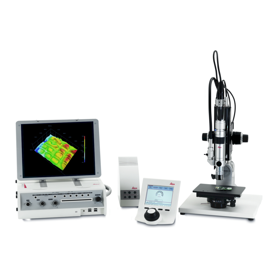
Basic System Configuration The basic configuration of Leica DVM5000 is shown below. Camera cable Fiber cable Camera High-resolution camera (2.11 million pixels) Lens (option) Select the lens suitable for the required magnification. Stand (option) Used to fix the camera or lens. - Page 15 Basic System Configuration Motorized focus drive and Leica SmartTouch Allows the Leica DVM5000 to move the lens in Z direction. ACS compatible lens (ACS: Auto Calibration Select) Dedicated cable Enables automatic calibration according to the lens magnifica- Supplied with the ACS compatible lens tion.
-
Page 16: Part Names And Functions
Provides operating buttons like POWER and SHUTTER buttons, and interface like DVD/CD slot and USB connector. Carrying handle Hold the handle when carrying the Leica DVM5000. Back panel Provides the main power switch, and interface such as printer connector and RGB connector. - Page 17 2 3 4 Part Names Function POWER button Turns ON/OFF the power to Leica DVM5000. Make sure the main power switch is set to ON. When LED is lit: Power ON When LED is not lit: Power OFF LAMP LED Lit while the metal halide lamp is ON.
- Page 18 BRIGHTNESS control Allows you to adjust brightness of camera image when the shutter speed adjustment method has been set to automatic (AUTO). The more the control is turned toward MAX, the brighter the image is. Leica DVM-series Setup Manual...
- Page 19 Normally, “0” must be set. The screen resolution changes automatically. RGB connector Connect the RGB cable to this connector. Main power switch Turns ON/OFF the power to Leica DVM5000. Light source connector Connect the fiber cable to this connector. Leica DVM-series...
-
Page 20: Installing The Leica Dvm5000
100 mm 100 mm Front view Mounting spacer bars prevents damage to cables that may be caused as the Leica DVM5000 is pressed against the wall. A total of four spacer bars can be mounted. Mount point Mount point Spacer bar... - Page 21 Installing the Leica DVM5000 Using the Monitor Hold the monitor with both hands. Slide the open/close knob outward to open the monitor. While holding down both sides of the monitor, tilt it. Open/close knob Place the monitor positioning hook into the slot so that the monitor is tilted at an appropriate angle.
-
Page 22: Connecting Peripheral Devices
Connecting the Dedicated Cable of the ACS Compatible Lens (Option) Insert the dedicated cable supplied with the ACS compatible lens into the Leica DVM Control Unit and connect then to the Leica DVM5000. For the connection method for the ACS compatible lens and dedicated cable, refer to the instruction manual supplied with the lens. - Page 23 To disconnect the plug, loosen the screw and pull the plug out straight. Connecting the Fiber Cable Insert the fiber plug into the light source connector, and turn the fixing ring to secure the fiber plug. Fixing ring Leica DVM-series Setup Manual...
- Page 24 Connecting Peripheral Devices Connecting the Power Cable Connect the power cable to the Leica DVM5000 as follows. Insert the AC power cable plug Insert the power cable to a 3-pin AC power outlet into the AC inlet. (that has a grounding terminal)
- Page 25 Connect the USB cables of input devices to USB connectors on the Leica DVM5000. • The Leica DVM5000 has four USB connectors on the front panel and two on the back panel. Any USB connectors can be used.
- Page 26 • Printing may not work properly depending on the printer connected. • Connect the type-B connector of the USB cable to Leica DVM5000, and the type-A connector to the printer. • For the printer setting/handling methods, refer to the Opera- tion Manual and the manual supplied with the printer.
- Page 27 Connecting Peripheral Devices Connecting a 2 Axis Motor Controller (Option) Insert the RS-232C cable supplied with the 2 axis motor controller (CT-7) into the AUX connector on the Leica DVM5000. Insert the RS-232C cable into the AUX connector. Turn the screw to secure the cable plug.
- Page 28 Connect the LAN cable to the Ethernet connector. sure that the LAN cable type (cross/straight) is correct. Leica DVM5000 can be connected directly or via HUB to the personal • Moving images cannot be recorded directly to the shared computer.
- Page 29 Commercially available DVDs and CDs can be used. Still and moving • If the DVD/CD still has some free space after writing, it is images recorded on the hard disk of Leica DVM5000 can be copied to a possible to add data to it. Some media types allow deletion of DVD/CD.
- Page 30 Connect the USB cable of the mass-storage device to a USB connector on the Leica DVM5000. • The Leica DVM5000 has four USB connectors on the front panel and two on the back panel. Any USB connectors can be used.
- Page 31 Terminal name Spare Freeze terminal Still image recording terminal Spare Spare Common terminal Appropriate Connector Manufacturer Model Hirose Electric Co., Ltd. SR30-10PG-6P Connection Example 3 Still image recording terminal 2 Freeze terminal 6 Common terminal Switch, etc. Leica DVM-series Setup Manual...
-
Page 32: Maintenance
After the power is turned ON, make sure that the fan inside the Leica DVM5000 is rotating. If it is not rotating, the Leica DVM5000 may be faulty. In this case, contact your Leica Microsystems representative. Check for collection of foreign matter on the camera and lens. If foreign matter has collected on the camera or lens, Camera, lens remove it using a cotton swap or blower. - Page 33 • Insert screw A into the notch in the bottom of the lamp holder and push the lamp frame (area B in the illustration) towards the lamp before tightening the screw. Leica DVM-series Setup Manual...
-
Page 34: Troubleshooting
This section explains problems that may occur during operation of the Leica DVM5000, along with their corrective actions. Refer to this section before sending the Leica DVM5000 for repair. If the problem still occurs, contact your Leica Microsystems representative. When Power is Turned ON... - Page 35 Cause and Action Reference Not possible to print. • The USB cable is not connected to the printer or to the Leica DVM5000. P 26 Make sure that the USB cable is connected to both the printer and Leica DVM5000.
-
Page 36: Specifications And Dimensions
UXGA, SXGA, XGA Printer output USB (B-type), PictBridge compatible 10BASE-T, 100BASE-TX, 1000BASE-T RS-232C connector Input Mouse USB (A type) Keyboard USB (A type) Microphone MIC input jack External remote 6-pin, round terminal ACS terminal 10-pin, round Leica DVM-series Setup Manual... - Page 37 • Installation category II • Pollution degree 2 • Supply voltage fluctuations ±10% of the rated voltage • Degree of protection IP20 Protection class Class I Weight Main body Approx. 12 kg Camera unit Approx. 1 kg (including cables) Leica DVM-series Setup Manual...
-
Page 38: External Dimensions
Specifications and Dimensions External Dimensions Leica DVM5000 When monitor is closed (420.4) 41.4 (154) When monitor is open (90°) Leica DVM-series Setup Manual... - Page 39 Specifications and Dimensions Fiber Camera 1/4-20UNC depth 5.5 Minimum bending radius R=70 Cable length 2000 Leica DVM-series Setup Manual...
-
Page 40: Usable Detachable Power Supply Cord Set
Note: * 1. Be sure that the detachable proper Supply cord has the approval of the appropriate safety agencies of the country where the equipment will be used. * 2. Cable length of above Power Supply cord shall be shorter than 3 m. Leica DVM-series Setup Manual... - Page 41 Usable Detachable Power Supply Cord Set Certification Marking Country Agency Certification Mark Country Agency Certification Mark Austria Italy Belgium CEBEC Norway NEMKO Denmark DEMKO Spain Finland Sweden SEMKO France Switzerland Germany Leica DVM-series Setup Manual...
- Page 42 Revision History Revision Code Date Revised contents Januray 2010 Leica Original production Leica DVM-series Setup Manual...
- Page 43 Leica DVM-series Setup Manual...
Need help?
Do you have a question about the DVM5000 and is the answer not in the manual?
Questions and answers