
Related Manuals for IDEAL 61-517 GFCI


Summary of Contents for IDEAL 61-517 GFCI
- Page 1 ® IDEAL Test and Measurement 61-517 GFCI Receptacle/VoltageTester Operation and Safety Manual Instrucciones en español adentro / Instructions en français à l’intérieur...
- Page 2 Notes...
-
Page 3: Table Of Contents
Introduction ..........3 Contacting IDEAL INDUSTRIES, INC ....3 Safety Information ........4 Warnings ...............5-6 Cautions ..............6 Symbols ..............7 Operation..........8-15 Identification and description of operating controls and functions ..........8-9 Operating Features ..........10 Meter Operation ..........11-12 Voltage and Polarity ........11 Testing a GFCI .......... -
Page 4: Introduction
Introduction The IDEAL 61-517 GFCI Receptacle Tester is a 120V AC plug in outlet tester that indicates proper polarity or mis-wired outlets via Green and Red LEDs and line voltage via a LCD. It also tests for GFCI functioning. Arc Flash and Shock Hazard, Proper PPE Required. Follow all safety procedures, wear proper PPE in accordance to NFPA 70E. -
Page 5: Safety Information
Safety Information Warning - Identifies conditions and actions that could result in possible death or serious injury if the hazard is realized. Caution - Identifies conditions and actions that could result in meter damage, equipment under test damage or data loss if the hazard is realized. -
Page 6: Warnings
WARNING Arc Flash and Shock Hazard, Proper PPE Required. Follow all safety procedures, wear proper PPE in accordance to NFPA 70E and follow the guidelines below and the instructions in this manual when operating the meter. Failure to comply can result in serious injury or death. -
Page 7: Symbols
Symbols & Descriptions SYMBOL DESCRIPTION Arc Flash and Shock Hazard Shock Hazard Warning or Caution Choking Hazard AC (Alternating Current) Low Battery Indicator Earth Ground CAT II IEC Measurement Category II CAT II has protection against transients in fixed and non-fixed powered devices including appliances, lighting, and 120V or 240V equipment inside a building. -
Page 8: Operation
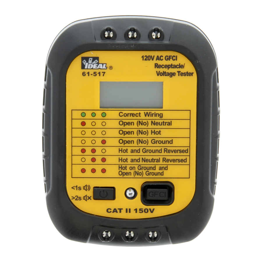
Operation Identification and Description of Operating Controls and Functions for the 61-517 GFCI Receptacle/ Voltage Tester: On Off Button GFCI Test Active LED GFCI Test Button Polarity Legend AC Voltage LCD Red-Green Polarity Indicator LEDs Hot-Neutral-Ground Prongs... -
Page 10: Operating Features
Operating Features High Voltage Warning (HI-V) The meter indicates a when measuring ~120V AC Backlight Backlight is always on when meter is functioning. -
Page 11: Meter Operation
Meter Operation Voltage and Polarity First, turn the meter on by pressing the ON/OFF Button and then insert into an outlet. If the batteries are good, the 61-517 will beep continuously to indicate live voltage, display the correct voltage, and indicate 3 bright green LEDS on the top and the bottom IF the HOT NEUTRAL and GROUND polarity of the outlet is correct. -
Page 12: Testing A Gfci
Testing a GFCI Turn the unit on. Insert the unit into a live GFCI receptacle. Confirm that the 3 polarity indicators are all green. Press and hold the GFCI button for 6 seconds or until the GFCI trips. The light next to the GFCI button will turn RED until the GFCI trips. -
Page 13: Polarity Indications Table
Polarity Indications Table Wire Indication When Plugged Into Outlet (Values Maintained for 5 Condition Seconds After Unplugging from Outlet) LED Indication Buzzer LCD display Green (G) Red (R) Off (O) 1. If Voltage is between 85 1. 5s continuous beep ~ 150VAC, LCD Displays (if Voltage between 108 Correct Wiring... -
Page 14: Functions Operation Table
Functions Operation Table Default Button Response Operation Function 1) Press the on button for Turns ON longer than 2 sec. The unit will turn on and be in the silent mode. 2) Press the ON button for Silent Mode Audible less than 1 sec. -
Page 15: Electrical Specifications
Function Range Resolution Accuracy 61-517 ±(a%+b) AC Voltage (V) 150V ±(3.0%+2) GFI (mA) 6mA~9mA 102V,>6.0mA ±(2.0%+5) Environmental Specifications 32ºF to 104ºF (0ºC to 40ºC) Operating Temperature: (<80%RH) Operating Altitude: 6500 ft (2000 m) 14ºF to 122ºF (-10ºC to 50ºC) Storage Temperature: (<80%RH) Intended for indoor use. -
Page 16: Mechanical
Mechanical Specifications 3.25 in. x 2.6 in. x 1.25 in. Dimensions: (L x W x H) (85 mm x 65 mm x 33 mm) Weight: 0.25 LBS (0.1 KG) Display: Display Count: Power Source: 2 x 1.5V AAA Battery Life: 100 Hours Typical EMC/EMI CISPR 22 3rd Edition. -
Page 17: Maintenance And Service
Inspect the insertion prongs and ground pin for any signs of corrosion and for straightness. If the blades are bent, do no use the unit. Return to IDEAL for service. Battery Inspection/Replacement Inspect the battery compartment monthly for any signs of degradation. -
Page 18: Disposal And Warranty
This warranty constitutes the sole and exclusive remedy of the purchaser and the exclusive liability of IDEAL, and is in lieu of any and all other warranties, and expressly disclaims all other warranties, implied, or statutory as to merchantability, fitness for purpose sold, description, quality productiveness, or any other matter. - Page 20 ® IDEAL Prueba y Medición 61-517 GFCI Manual de Operación y Seguridad del Comprobador de Receptáculo GFCI/Voltaje Instrucciones en español adentro / Instructions en français à l’intérieur...
- Page 21 Notes...
- Page 22 Índice Introducción ............23 Cómo contactar a IDEAL INDUSTRIES, INC....23 Información de Seguridad ........24 Advertencias ..............24-25 Precauciones ................25 Símbolos ................26 Operación ............ 27-34 Identificación y descripción de controles de operación y funciones................ 27-28 Funciones de Operación ............29 Operación del Medidor ...........
-
Page 23: Introducción
Introducción El Probador de Receptáculos GFCI 61-517 de IDEAL es un probador de tomacorriente de 120V CA enchufable que indica la polaridad adecuada o tomas de corriente mal cableadas a través de LEDs verdes y rojos y voltaje de línea a través de un LCD. También prueba el funcionamiento de GFCI. -
Page 24: Información De Seguridad
Información de Seguridad Advertencia - Identifica condiciones y acciones que podrían provocar la muerte o lesiones graves si se toma el riesgo. Precaución - Identifica condiciones y acciones que podrían resultar en daño al medidor, daño al equipo bajo prueba o pérdida de datos si se toma el riesgo. -
Page 25: Advertencias
ADVERTENCIA Peligro de Arco Eléctrico y Descarga Eléctrica, se Requiere el EPP Adecuado. Siga todos los procedimientos de seguridad, use el EPP adecuado de acuerdo con NFPA 70E y siga las pautas a continuación y las instrucciones de este manual cuando opere el medidor. El incumplimiento puede resultar en lesiones graves o la muerte. -
Page 26: Símbolos
Símbolos y Descripciones SÍMBOLO DESCRIPCIÓN Peligro de Arco Eléctrico y Descarga Eléctrica Peligro de Descarga Eléctrica Advertencia o Precaución Peligro de Asfixia CA (Corriente Alterna) Indicador de Nivel de las Baterías Tierra CAT II Categoría de Medición IEC II CAT II tiene protección contra transitorios en dispositivos fijos y no fijos, incluyendo electrodomésticos, iluminación y equipos de 120V o 240V dentro de un edificio. -
Page 27: Operación
Operación Identificación y Descripción de Controles de Operación y Funciones del Probador de Receptáculo GFCI/Voltaje 61-517: Botón de Encendido/Apagado Prueba GFCI LED Activo Botón de prueba GFCI Leyenda de Polaridad Voltaje de CA LCD LEDs Indicadores de Polaridad Rojo-Verde Clavijas Caliente-Neutral-Tierra... -
Page 29: Funciones De Operación
Funciones de Operación Advertencia de Alto Voltaje (HI-V) El medidor indica un cuando se mide ~120V CA Luz de Fondo La luz de fondo siempre está encendida cuando el medidor está funcionando. -
Page 30: Operación Del Medidor
Operación del Medidor Voltaje y Polaridad Primero, encienda el medidor pulsando el botón ON/OFF y, a continuación, insértelo en un tomacorriente. Si las baterías están buenas, el 61-517 pitará continuamente para indicar voltaje vivo, mostrar el voltaje correcto e indicar 3 LED verdes brillantes en la parte superior e inferior SI la polaridad CALIENTE, NEUTRAL y TIERRA de la salida es correcta. -
Page 31: Probar Un Gfci
Probar un GFCI Encienda la unidad. Inserte la unidad en un receptáculo GFCI vivo. Confirme que los 3 indicadores de polaridad estén todos verdes. Mantenga pulsado el botón GFCI por 6 segundos o hasta que el GFCI se dispare. La luz junto al botón GFCI se volverá ROJA hasta que el GFCI se active. -
Page 32: Tabla De Indicaciones De Polaridad
Tabla de Indicaciones de Polaridad Condición de Indicación al Estar Enchufado en el tomacorriente Alambre (Valores Mantenidos Durante 5 Segundos Después de Desconectar del tomacorriente) Indicador LED Zumbador Pantalla LCD (encendido sólido) Verde (G) Roja (R) Apagado (O) 1. Si el voltaje está entre 1. -
Page 33: Tabla De Operaciones De Funciones
Tabla de Operaciones de Funciones Función Botón Respuesta Operatción Predeterminada 1) Presione el botón de Enciende Apaga ENCENDIDO durante más de 2 seg. La unidad se encenderá y estará en modo silencioso. 2) Presione el botón de Modo Audible ENCENDIDO durante menos de Silencioso 1 seg. -
Page 34: Especificaciones Eléctricas
Función Rango Resolución Precisión 61-517 ±(a%+b) Voltaje CA (V) 150V ±(3.0%+2) GFI (mA) 6mA~9mA 102V,>6.0mA ±(2.0%+5) Especificaciones Ambientales 32ºF a 104ºF (0ºC a 40ºC) Temperatura Operativa: (<80%RH) Altitud Operativa: 6500 pies (2000 m) Temperatura de Almace- 14ºF a 122ºF (-10ºC a 50ºC) namiento: (<80%RH) Destinado para uso en interiores. -
Page 35: Especificaciones Mecánicas
Especificaciones Mecánicas Dimesiones: (L x An x Al) 3.25 pulg. x 2.6 pulg. x 1.25 pulg. (85 mm x 65 mm x 33 mm) Peso: 0.25 LBS (0.1 KG) Pantalla: Conteo de Pantalla: Fuente de Alimentación: 2 x 1.5V AAA Vido Útil de las Baterías: 100 Horas Típico EMC/EMI... -
Page 36: Mantenimiento Y Servicio
Examine las clavijas de inserción y el pin de tierra por cualquier muestra de corrosión y por rectitud. Si las hojas están dobladas, no use la unidad. Devuelva a IDEAL para servicio. Inspección/Reemplazo de las Baterías Inspeccione el compartimiento de las baterías mensualmente por cualquier seña de degradación. - Page 37 Esta garantía constituye el único y exclusivo recurso del comprador y la responsabilidad exclusiva de IDEAL, y sustituye a todas y cada una de las otras garantías, y renuncia expresamente a todas las demás garantías, implícitas o reglamentarias en cuanto a comerciabilidad, idoneidad para el propósito vendido, descripción, productividad...
- Page 39 ® Test et Mesurage IDEAL 61-517 GFCI Manuel d’utilisation et de sécurité du détecteur de tension/réceptacles GFCI Instrucciones en español adentro / Instructions en français à l’intérieur...
- Page 40 Notes...
- Page 41 Table des Matières Introduction ............42 Contacter IDEAL INDUSTRIES, INC ......42 Informations de sécurité ........43 Avertissements ...............43-44 Précautions ................. 44 Symboles ................45 Mise en exploitation.........46-52 Identification et description des contrôles d’exploitation et fonctionnalités ..............46-47 Caractéristiques d’exploitation..........48 Exploitation du compteur..........48-49 Tension et polarité...
-
Page 42: Introduction
Introduction Le détecteur de réceptacles IDEAL 61-517 GFCI est un détecteur de prise de courant alternatif de 120 V qui indique la polarité appropriée ou les prises mal câblées via les D.E.L. vertes et rouges et la tension de ligne à travers un écran LCD. Il teste également le fonctionnement du GFCI. -
Page 43: Informations De Sécurité
Consignes de Sécurité Avertissement - Identifie les conditions et les actions qui pourraient entraîner la mort ou des blessures graves si le danger a lieu. Attention - Identifie les conditions et les actions qui pourraient entraîner des dommages au détecteur, des dommages aux équipements testés ou la perte de données si le danger a lieu. -
Page 44: Précautions
ATTENTION Risque d’éclair d’arc électrique et de choc, EPI approprié requis. Suivez toutes les procédures de sécurité, portez l’EPI approprié conformément à la norme NFPA 70E et suivez les directives ci-dessous et les instructions de ce manuel lorsque vous utilisez le compteur. Le non-respect de cette règle peut entraîner des blessures graves voire mortelles. -
Page 45: Symboles
Symboles et Descriptions SYMBOLES DESCRIPTION Risque d’arc électrique et d’électrocution RIsque d’électrocution Avertissement out mise en garde Risque de suffocation AC (courant alternatif) Indicateur de batterie faible Point de mise à la terrie CAT II Catégorie de mesure II CEI CAT II offre une protection contre les transitoires dans les appareils alimentés fixes et non fixes, y compris les appareils électroménagers, l’éclairage... -
Page 46: Mise En Exploitation
Fonctionnement Identification et description des commandes de fonctionnement et des fonctions du détecteur de prise/tension GFCI 61-517: Bouton marche/arrêt D.E.L. active de test GFCI Bouton de test GFCI Légende de la polarité ACL de tension CA D.E.L. d’indication de polarité rouge-vert Broches de mise à... -
Page 48: Caractéristiques D'exploitation
Caractéristiques d’exploitation Avertissement de haute tension (HI-V) Le détecteur indique en lors de la mesure de ~120V AC Rétroéclairage Le rétroéclairage est toujours allumé lorsque le détecteur est en service. -
Page 49: Tension Et Polarité
Fonctionnement du détecteur Tension et polarité Tout d’abord, allumez le détecteur en appuyant sur le bouton MARCHE/ARRÊT, puis insérez-le dans une prise. Si les piles sont bonnes, le 61-517 émet un bip continu pour indiquer la tension d’alimentation, affiche la tension correcte et indique 3 D.E.L. vert brillant en haut et en bas SI la polarité... -
Page 50: Tester Un Gfci
Tester un GFCI Allumer l’appareil. Insérez l’appareil dans une prise GFCI sous tension. Vérifiez que les 3 indicateurs de polarité soient tous verts. Appuyez sur le bouton GFCI et maintenez-le enfoncé pendant 6 secondes ou jusqu’à ce que le GFCI se déclenche. Le voyant à côté du bouton GFCI deviendra ROUGE jusqu’à... -
Page 51: Tableau Des Indications De Polarité
Tableau des indications de polarité Câble des valeurs Indication lorsqu’il est branché sur une prise (condition maintenue pendant 5 secondes après la déconnexion de la prise) LED affichage Bipeur Affichage ACL Verte (G) Rouge (R) De (O) 1. Si la tension est comprise 1. -
Page 52: Tableau De Fonctionnalités D'exploitation
Tableau de fonctionnalités d’exploitation Fonction Bouton Réponse Fonctionnement par défaut 1) Appuyez sur le bouton marche S’allume pendant plus de 2 secondes. L’appareil s’allumera et sera en mode silencieux. Mode Audible 2) Appuyez sur le bouton Allumé silencieux pendant moins de 1 seconde. L’appareil s’allumera et sera en mode audible. -
Page 53: Caractéristiques Électriques
Foncionnalité Plage Résolution Précision 61-517 ±(a%+b) Tension AC (V) 150V ±(3,0%+2) GFI (mA) 6mA~9mA 102V >6,0mA ±(2,0%+5) Caractéristiques Environnementales 0 °C à 40 °C (32 °F à 104 °F) Température de fonctionnement : (< 80 % RH) Altitude d’exploitation : 2000 m (6500 pieds) -10 °C à... -
Page 54: Caractéristiques Mécaniques
Caractéristiques Mécaniques Dimensions: (L x P x H) 3,25 pounces x 2,6 pounces x 1,25 pounces (85 mm x 65 mm x 33 mm) Poids : 0,1 kg (0,25 lbs.) Affichage : Nombre affichage : Source d’alimentation : 2 x 1,5V AAA Vie de la batterie : 100 heures typiquement EMC/EMI... -
Page 55: Entretien Et Réparation
Inspecter les broches d’insertion et la broche de mise à la terre pour tout signe de corrosion et pour la rectitude. Si les lames sont pliées, ne pas utiliser l’appareil. Renvoyez-le à IDEAL pour réparation. Inspection/Rechange de la batterie Inspecter le compartiment de la batterie une fois par mois pour tout signe de dégradation. - Page 56 (2) ans à compter de la date d’achat. Avec une preuve d’achat d’un distributeur agréé d’IDEAL, un détecteur défectueux sera réparé ou rechangé par le même produit ou un produit fonctionnellement équivalent, au choix d’IDEAL INDUSTRIES, INC.
Need help?
Do you have a question about the 61-517 GFCI and is the answer not in the manual?
Questions and answers