Advertisement
Available languages
Available languages
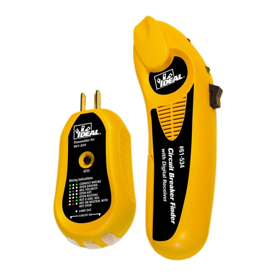
Automatic Circuit Identifier
With Digital Receiver and
120V GFCI Receptacle Tester
The task of locating AC circuits is now made quick and easy. No more guessing
or trial and error when it comes to locating the correct circuit breaker supplying
power to an AC outlet or lighting fixture.
WARNING: Read and understand operating instructions before using product.
WARNING: Use extreme care when working around AC circuits, severe shock
hazards exist. If used on a circuit controlled by a dimmer, turn the dimmer to the
highest on position. Do not use in cardiac care areas. Do not use during electrical storms or in wet weather
• Do not use around explosive gas, dust, vapor or in damp or wet environments. Do not submerge or expose the meter
to water and do not use if the meter has ever been exposed to water or other fluids.
• Do not apply more than the rated voltage.
• Voltages exceeding 30VAC or 60VDC pose a shock hazard so use caution.
Features:
• Automatically and quickly indicates the correct breaker
• Non-contact voltage sensor from 80-300VAC
• Transmitter works on 120VAC Hot to Neutral circuits
• Tests GFCIs wired to 3 conductors with a continuous ground
path back to the panel.
• Verifies wiring configuration
• Low battery indicator
OPERATION:
Self-Test
Depress the receiver's power switch forward to the ON position. The unit will perform a self-test to ensure proper operation.
Low Battery Detection
After performing the self-test, the receiver will verify the voltage of the 9Vdc battery. If the battery voltage is below 7.3 volts, the
receiver will beep three times and turn itself off. Remove the old battery, and replace it with a standard 9Vdc battery.
Idle Mode
Provided the battery is good, the receiver will enter the idle mode. Both the receiver's LEDs will remain on and the receiver will
continually check for any active signals.
Non-Contact Voltage Test
Point the receiver's nose towards a live AC receptacle or power cord. Once an AC Voltage field of > 80V is sensed, the receiver will
switch to Voltage Sensor mode. The red LED remains lit and the receiver will beep. The beeping speed increases when the receiver
is moved closer to the AC power source, and slows when the receiver is moved further away. Once the receiver senses a signal
from the transmitter, it will switch to the circuit identifier mode. The circuit identifier mode is indicated by a steady green LED.
Note that if a steady Green light is on, then the unit is no longer in the Non-Contact Voltage (NCV) function. To re-enter NCV
mode, power the unit off and then on again. Certain loads mimic the breaker mode signal and may cause the unit to exit NCV
mode and enter the breaker search mode, even if the transmitter is not plugged in. Use caution if the unit indicates that no voltage
is present. Always verify that the green light is not on when using the NCV function.
Locating A Circuit Breaker or Fuse:
1. Plug the transmitter into the receptacle.
2. Go to the circuit breaker panel box.
3. Turn the receiver on and allow it to complete its self-test away from power.
4. Place the flat surface of the tapered end of the receiver directly onto the circuit
breaker or fuse as shown. If the receiver is held at any other angle, inaccurate
readings may occur.
5. Slide the nose of the receiver down each breaker along both sides of the panel. Note
that the receiver will beep frequently as it measures the relative signal strength.
6. Move the receiver down each breaker once more. On the second pass, the receiver
will beep and the green LED will flash only at the circuit breaker powering
the transmitter.
7. Trip the breaker off and check that the LED's of the transmitter in the outlet are off to confirm you have selected the correct
breaker or fuse.
Locating a Circuit Breaker or Fuse Controlling an Incandescent Light Fixture
1. If the incandescent light fixture is controlled by a wall switch, make sure the wall switch is OFF.
2. Remove light bulb.
3. Install a Screw-in socket adapter (not included).
4. Plug the transmitter into the adapter. Note that a 3 prong to 2 prong adapter will be required.
5. Turn on the wall switch and follow the procedure described in Locating a Circuit Breaker or Fuse, steps 3 through 7.
NEVER plug the transmitter into the output of a dimmer switch or lighting ballast. Damage to the transmitter may occur.
Receiver Auto Power Off:
If the receiver is left on and not utilized for 10 minutes (no energized AC circuit or transmitter signals are detected), it will
automatically shut down to conserve its battery life.
Battery Replacement:
Unscrew and remove battery cover. Insert new 9V battery into battery compartment and re-install battery cover.
Red LED
Power Switch
Green LED
61-534
LEDs
Battery Compartment
Advertisement
Table of Contents

Related Manuals for IDEAL 61-534


Summary of Contents for IDEAL 61-534
- Page 1 61-534 Automatic Circuit Identifier With Digital Receiver and 120V GFCI Receptacle Tester The task of locating AC circuits is now made quick and easy. No more guessing or trial and error when it comes to locating the correct circuit breaker supplying power to an AC outlet or lighting fixture.
- Page 2 61-534 Identificador automático de circuitos con Receptor Digital y Probador de Tomas ICFT 120V La tarea de localizar circuitos de CA es ahora rápida y sencilla. No más adivinación ni prueba y error cuando se trata de localizar el disyuntor correcto que suministra alimentación a un tomacorriente o artefacto luminoso.
- Page 3 61-534 Identificateur de circuit automatique avec récepteur numérique et testeur de prises différentielles 120 V Le repérage des circuits c.a. est désormais plus rapide et plus facile. Plus d’incertitude et de tâtonnements pour localiser le disjoncteur correspondant à une prise ou un appareil d’éclairage c.a.
- Page 4 Register your product at: http://www.idlim.net/support/registration/. Any implied warranties arising out of the sale of an IDEAL product, including but not limited to implied warranties of merchantability and fitness for a particular purpose, are limited to the above. The manufacturer shall not be liable for loss of use of the instrument or other incidental or consequential damages, expenses, or economic loss, or for any claim or claims for such damage, expenses or economic loss.
- Page 5 IDEAL INDUSTRIES, INC. es su prueba de compra. Registre su producto en http://www.idlim.net/support/registration/. Cualquier garantía implícita originada en la venta de un producto IDEAL, incluyendo -pero sin limitarse a ellas- garantías implícitas de comerciabilidad y adecuación para un propósito particular, se limitan a lo indicado anteriormente. El fab- ricante no será...
- Page 6 à http://www.idlim.net/support/registration/. Toutes les garanties implicites résultant de la vente d’un produit IDEAL, incluant sans y être limitées les garanties implicites de valeur marchande et d’adaptation à une fin particulière, sont limitées aux conditions ci-dessus. Le fabricant ne sera pas tenu pour responsable de la perte d’usage de l’instrument, ni d’autres dommages accessoires ou indirects, dépenses ou préjudice financier, ou de toute(s)
Need help?
Do you have a question about the 61-534 and is the answer not in the manual?
Questions and answers