Table of Contents
Advertisement
Quick Links
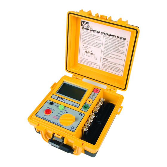
Earth Ground Resistance Tester
Instruction Manual
796 FEATURES
•
Measures ground rod resistance using 3-poles
•
Measures earth voltage
•
Does not trip ground fault breakers in the
circuit under test
•
Includes test leads and electrodes
•
0
Ω adjustment
•
Data hold
•
Low battery indicator
Read First: Safety Information
Understand and follow operating instructions carefully. If this tester is not used in a manner
specified by IDEAL, protection provided by the product may be impaired.
WARNING
To avoid possible electric shock, personal injury or death, follow these instructions:
• Do not use if tester appears damaged. Visually inspect the tester to ensure case is not
cracked and back case is securely in place.
• Inspect and replace leads if insulation is damaged, metal is exposed, or probes are
cracked. Pay particular attention to the insulation surrounding the connectors.
• A shock hazard exists during normal testing as a voltage is present across the measuring
terminals.
• Do not use tester if it operates abnormally as protection maybe impaired.
• Do not use during electrical storms or in wet weather.
• Do not use around explosive gas, dust, or vapor.
• Do not use tester on energized circuits.
• Do not use without the battery and the back case properly installed.
• Replace battery as soon as the low battery indicator "
readings.
• Remove the test leads from unit prior to removing battery cap.
• Use the proper terminals, function and range for your measurements.
• Do not attempt to repair this unit as it has no user-serviceable parts.
• Comply with local and national safety requirements, including the use of appropriate
personal protective equipment.
#61-796
" appears to avoid false
CAUTION
To protect yourself, think "Safety First":
• Voltages exceeding 30VAC or 60VDC pose a shock hazard so use caution.
• Use appropriate personal protective equipment such as safety glasses, face shields,
insulating gloves, insulating boots, and/or insulating mats.
• Never ground yourself when taking electrical measurements.
• Always work with a partner.
• When using the probes, keep fingers as far behind the probe tips as possible.
Operating Instructions
• Before proceeding with
measurement, if the
"
" symbol appears on
the display, replace with new
batteries.
• Short the tips of the leads.
Adjust the 0Ω. ADJ control to
set the reading to zero.
• Rotate the function switch to the "EARTH VOLTAGE" position and press to test. Earth volt-
age will be displayed on the LCD. If earth voltage is more than 10V, an inaccurate reading
may be obtained.
• Precision earth resistance measurement method:
(1) Connect the green, yellow and red test leads to instrument terminals E, P and C with
auxiliary earth spikes P1, C1 placed into the soil "IN A STRAIGHT LINE". (Fig. 1)
(2) Rotate the function switch to a suitable range then press the pushbutton to test and
take the reading.
•
Simplified earth resistance measurement method
(1) This method is recommended where an earth resistance higher than 10Ω is
measured or where it is not possible to drive auxiliary earth spikes. An approximate
value of earth resistance can be obtained by the two wire system shown in Fig. 2.
(2) Rotate the function switch to "EARTH VOLTAGE" position and press to test. Make
certain that earth voltage is less than 10V.
(3) First rotate the function switch to the "200Ω" position and press to test. Read earth
resistance. If the display shows "1" (MSD), switch to the "2KΩ" position and read
earth resistance.
(4) The reading obtained (Rx) is an
approximate earth resistance
value. There is no need for
external shorting as P and C
terminals are shorted by
using the test leads
specified for the simplified
measurement.
Figure 1
Green
Yellow
Red
E
P
C
Auxiliary
5-10m 5-10m
Earth
Spikes
Green
Secondary
Red
Side
re
Rx
C
E
P
Earth
Electrode
under test
Where earth for mains power
supply is used.
2
Earth
Electrode
under test
Figure 2
Rx = Re-re
Primary
Side
Supply
Transformer
Advertisement
Table of Contents

Subscribe to Our Youtube Channel
Related Manuals for IDEAL 61-796


Summary of Contents for IDEAL 61-796
-
Page 1: Instruction Manual
Understand and follow operating instructions carefully. If this tester is not used in a manner • Precision earth resistance measurement method: specified by IDEAL, protection provided by the product may be impaired. (1) Connect the green, yellow and red test leads to instrument terminals E, P and C with auxiliary earth spikes P1, C1 placed into the soil “IN A STRAIGHT LINE”. - Page 2 Earth voltage: 0~200V AC, 40-500Hz Any implied warranties arising out of the sale of an IDEAL product, including but not limited Accuracy: Earth resistance: ±(2%reading± 2digits) or ±0.1Ω, to implied warranties of merchantability and fitness for a particular purpose, are limited to the whichever is greater.
Need help?
Do you have a question about the 61-796 and is the answer not in the manual?
Questions and answers