Advertisement
Available languages
Available languages
Quick Links
Vol-Con
XL (61-086)
®
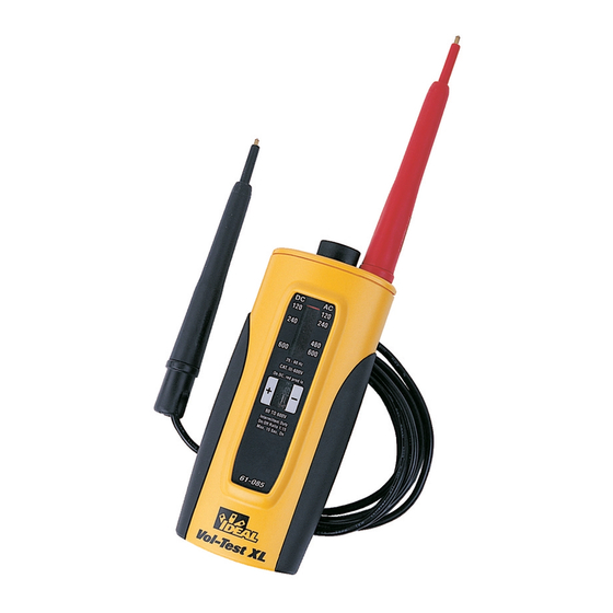
Voltage/Continuity Tester
and Vol-Test™ (61-085)
Voltage Tester
Instruction Manual
Register your product and access more
information at www.idealindustries.com
Read First: Safety Information
Understand and follow operating
instructions carefully. Use the tester and
test leads only as specified in this manual;
otherwise, the protection provided by the
tester can be impaired.
WARNING
To avoid possible electric shock,
personal injury or death, follow these
guidelines:
• Do not use if tester appears damaged.
Visually inspect the tester to ensure
case and is not cracked.
• Inspect and replace test leads if
insulation is damaged, metal is
exposed, or probes are cracked. Pay
particular attention to the insulation
surrounding the connectors.
• Always ensure the tester, test leads
and all accessories meet or exceed the
measurement category required in the
working environment. (i.e. CAT rating)
#61-085
• Note that the measurement category
#61-086
and voltage rating of combinations
of the tester, the test leads, and
the accessories is the lowest of the
individual components.
• Do not use tester if it operates
abnormally as protection maybe
impaired.
• Do not use during electrical storms or
in wet weather.
• Do not use around explosive gas, dust,
vapor, amperage or in damp or wet
environments.
• Do not apply more than the rated
voltage to the tester.
• Remove the test leads from the input
jacks before measuring current.
• Remove the test leads from the meter
prior to removing battery cover. (61-086)
• Do not use without the battery and
battery cover properly installed. (61-086)
• Do not attempt to repair this unit as it
has no user-serviceable parts.
• Never ground yourself when taking
electrical measurements.
• Connect the black common lead to
ground or neutral before applying
the red test lead to potential voltage.
Disconnect the red test lead from the
voltage first.
• When using the probes, keep fingers
behind the guard rings of the probe
tips.
• Voltages exceeding 30VAC or 60VDC
pose a shock hazard so use caution.
- 2 -
Advertisement

Related Manuals for IDEAL 61-085


Summary of Contents for IDEAL 61-085
-
Page 1: Instruction Manual
XL (61-086) ® individual components. Voltage/Continuity Tester • Do not use tester if it operates abnormally as protection maybe and Vol-Test™ (61-085) impaired. Voltage Tester • Do not use during electrical storms or Instruction Manual in wet weather. • Do not use around explosive gas, dust, Register your product and access more information at www.idealindustries.com... - Page 2 Symbols on the Unit CAUTION To protect yourself, think “Safety First”: Risk of Danger. Important Information. See Manual. • Comply with local and national safety codes. Hazardous voltage. • Use appropriate personal protective Application around and equipment such as face shields, removal from Hazardous Live insulating gloves, insulating boots, conductors is permitted.
- Page 3 • Connect the tester in parallel with Levels (61-085 has LED indica- the load or circuit. tion only). • The tester indicates the voltage • Auto-Switching Voltage/ type, polarity, and the voltage level. Continuity Technology (61-086 (See Tester Operation table) only) •...
- Page 4 tinuity check. If conti- nuity LED turns “On,” the fuse is good. If the continuity LED does Indicator not turn “On,” the fuse is defective. (61-086 only) With power on: Place tester across the “source” side of one fuse and the load side of an adjoining Neon Bulb fuse.
- Page 5 • Checking Continuity of Cords, Motors, Appliances, etc. (61-086 Test Lead Replacement: only) • Replace leads only with IDEAL test leads Remove power source and place tester below. across circuit to be tested. Continuity • # TL-80 Standard Test Leads with LED turns “On”...
-
Page 6: Specifications
Specifications: purchase. During this warranty period, VAC Ranges: 120V, 240V, 480V, 600V AC. IDEAL INDUSTRIES, INC. will, at its option, VAC Accuracy: Relative indication only replace or repair the defective unit, subject VDC Ranges: 120V, 240V, 600V DC to verification of the defect or malfunction. - Page 7 Probador de voltaje/continuidad Any implied warranties arising out of the Vol-Con® XL (61-086) y probador sale of an IDEAL product, including but not de voltaje Vol-Test™ (61-085) limited to implied warranties of merchant- Manual de instrucciones ability and fitness for a particular purpose, are limited to the above.
- Page 8 • Al usar las sondas, mantenga los dedos accesorios cumplan o excedan la categoría detrás de los anillos protectores en las de medición necesaria en el ambiente de puntas de las sondas. trabajo. (Por ejemplo, clasificación CAT) • Los voltajes superiores a 30 VCA o 60 •...
- Page 9 Para probar la continuidad: (61-086 • Indicación audible y de LED de niveles solamente) de voltaje (el 61-085 tiene una indicación • Asegúrese de que el enchufe de los cables LED solamente). de prueba esté completamente asentado en •...
- Page 10 automáticamente a la modalidad de indi- cación de voltaje. • Pruebe si existe continuidad conectando el probador al circuito. Indicador • Si el circuito tiene una resistencia de 500kW o menos, se oye una indicación audible y se enciende el LED de con- tinuidad.
- Page 11 corriente de 25 ciclos. La corriente de 60 Repita la misma prueba de arriba en el ciclos viene indicada por un zumbido de circuito trifásico. Una indicación de que mayor frecuencia y vibraciones más rápi- no hay voltaje o que es menor que el das.
- Page 12 Altitud: 2000m Uso interior Observe que los cables de prueba Pila: (4) 1.5V (IDEAL No. 61-201, IEC No. TL-80 y TL-82 sólo se pueden usar LR44, o NEOA No. 1166A). específicamente con los probadores el Duración de las pilas: 200 horas típico...
- Page 13 IDEAL INDUSTRIES, INC. reemplaz- (61-086) et testeur de ará o reparará la unidad defectuosa, a la sola tension Vol-Test™ (61-085) opción de IDEAL, sujeto a la verificación del defecto o falla. Mode d’emploi Esta garantía no cubre fusibles, baterías o Enregistrez votre produit et accédez...
- Page 14 accessoires correspondent ou sont • Quand on se sert des sondes, les doigts supérieurs à la catégorie de mesure doivent demeurer derrière les bagues de nécessaire dans le milieu de travail. protection des pointes de sonde. (c.-à-d. classification CAT) • Les tensions dépassant 30 V CA ou •...
- Page 15 • Indication de niveaux de tension par • Le testeur indique le type de tension, la signal sonore et DEL (61-085 a une polarité et le niveau de tension. (Voir la indication par DEL seulement). Table de fonctionnement du testeur) •...
- Page 16 Pour tester la continuité : (61-086 seulement) • S’assurer que la fiche des conducteurs d’essai est complètement enfoncée dans Indicator la prise banane. • Mettre le circuit hors tension avant de procéder à l’essai de continuité. Remarque : en présence de tension sur le circuit, le tes- teur passera automatiquement sur le mode d’indication de tension.
- Page 17 fusible voisin de la pointe de contact du chacune des connexions de bornes. La côté charge est fondu. Si une tension est borne qui ne produit pas d’indication de indiquée, le fusible voisin de la pointe de tension tout en produisant une indication contact du côté...
- Page 18 • Nettoyer le boîtier avec un chiffon • Remplacer les piles par 4 piles boutons humide et un détergent doux. N’utiliser ni neuves de 1,5 V (IDEAL N° 61-201, IEC abrasifs ni solvants. N° LR44 ou NEOA N° 1166A). Entretien-dépannage et pièces de •...
- Page 19 Le fabricant ne sera pas tenu Utilisation à l’intérieur pour responsable de la perte d’usage de Pile : (4) 1,5 V (IDEAL N° 61-201, IEC N° l’instrument, ni d’autres dommages acces- LR44 ou NEOA N° 1166A). soires ou indirects, dépenses ou préjudice Durée de service de la pile :...
Need help?
Do you have a question about the 61-085 and is the answer not in the manual?
Questions and answers
61-085 have a battery