Advertisement
SP158A, SPT15A,
SP308A, SPT30A
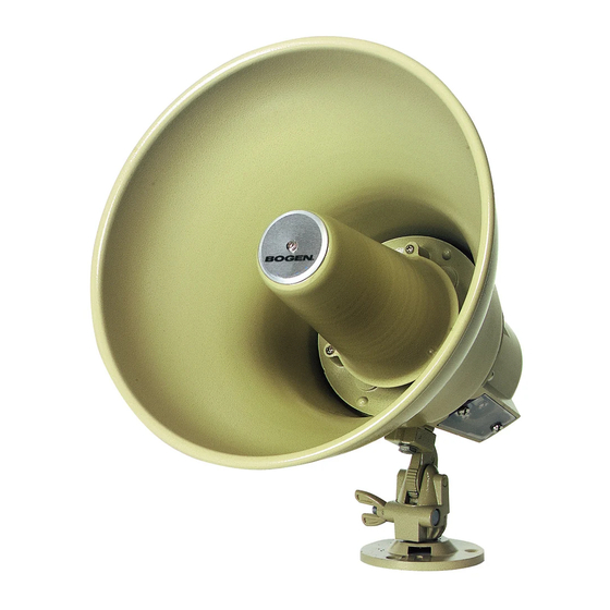
15/30-Watt Horn Loudspeakers
Installation Instructions
STEP 1 - For easier installation, remove the mounting base from the speaker by
unscrewing the wing nut while at the same time pressing inwardly on the wing nut.
Place the mounting base flush on the mounting surface and mark the location of the
three holes with either a marker or chisel. It is important that the three holes be
exactly aligned with the mounting base, otherwise you might stress the base or make
the connection unsteady. Use appropriate hardware for your specific mounting
surface.
NOTE: Speaker may also be strap-mounted through the slot in mounting base using
standard 1/2-inch industrial strapping (not included).
STEP 2 - After mounting the base, reattach the speaker and aim the speaker for the
desired coverage angle. A 45° downward angle is recommended, but this may vary
depending upon speaker layout. Unless otherwise indicated, do not aim speakers
directly at each other or poor paging intelligibility may occur.
STEP 3 - Remove the plastic cover to expose the connecting screws (see Figure 2). Strip
the ends of the connecting wires about 1/4" and connect them to the terminals.The
terminals are numbered to indicate phasing.
Provide cable strain relief by laying the cables within the recess on the casting and
holding it tight with the plastic cover.The narrow recess is for zip or two-conductor
cable; the wide recess is for shielded cable.
Connect wires as listed below:
Amplifier Output
70V, 25V, or 8 ohms
COM
NOTE: These are recommended connections.The speaker will also work perfectly well with these connections reversed, but be
consistent in wiring connections.
STEP 4 - Adjust the tap set control to the desired setting. See table (Figure 3 on next page) for tap settings and sound pressure lev-
els for the different horn loudspeakers. Replace the plastic protective cover back over the exposed area.
Speaker Connections
Terminal 1
Terminal 2
15W
Figure 1. Mounting Base and
Strap Mounting Slot
Figure 2. Tap Set Control and
Connecting Screw Terminals
(SPT15A/SPT30A only)
© 2007 Bogen Communications, Inc.
Specifications subject to change without notice.
54-5817-02B
30W
0704
Advertisement
Table of Contents

Related Manuals for Bogen SP158A


Summary of Contents for Bogen SP158A
-
Page 1: Installation Instructions
Replace the plastic protective cover back over the exposed area. Figure 1. Mounting Base and Strap Mounting Slot Figure 2. Tap Set Control and Connecting Screw Terminals (SPT15A/SPT30A only) © 2007 Bogen Communications, Inc. Specifications subject to change without notice. 54-5817-02B 0704... -
Page 2: Technical Specifications
Bogen's liability arising out of the manufacture, sale or supplying of products or their use or disposition, whether based upon warranty, contract, tort or otherwise, shall be limited to the price of the product. In no event shall Bogen be liable for special, incidental or conse- quential damages (including, but not limited to, loss of profits, loss of data or loss of use damages) arising out of the manufacture, sale or supplying of products, even if Bogen has been advised of the possibility of such damages or losses.
Need help?
Do you have a question about the SP158A and is the answer not in the manual?
Questions and answers