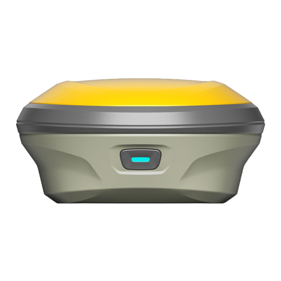
Summary of Contents for e-survey E500
- Page 1 E500 User Manual E500 GNSS Receiver User Manual V1.0_202012 Web: www.esurvey-gnss.com Email: support@esurvey-gnss.com...
-
Page 2: Table Of Contents
E500 User Manual Contents Introduction ......................1 Appearance ....................1 Indicator ......................1 Interface ......................2 Pin definition ....................2 Power button ....................3 Web User Interface ....................3 Position ......................4 Satellites ......................4 Information ....................5 Working Mode ....................5 Satellite Setting ..................... -
Page 3: Introduction
E500 User Manual 1. Introduction This is the user manual for survey E500 GNSS receiver. It gives basic description and operation guide which may help user to operate device properly. 1.1 Appearance The E500 main body is designed with magnesium alloy material to provide durable usage and better heat dispersion as well as light weight 1000g. -
Page 4: Interface
One solid green: battery level below 25% 1.3 Interface E500 GNSS receive bottom interface is shown as below. The 5-pin port is used to connect external radio and external power, or output NMEA messages. Type-C port can be used for data download (internal storage access) or charging. -
Page 5: Power Button
E500 User Manual 1.5 Power button There is a power button on E500 control panel, the main function as below: Long press button for three seconds then release Power On to power on receiver when it is powered off Long press button for three seconds, you'll hear Power Off "power off?"... -
Page 6: Position
E500 User Manual 2.1 Position View basic position information, satellite number, PDOP and time. In static mode, can start and stop recording here. 2.2 Satellites View satellite list and satellite map, set cut-off angle. Web: www.esurvey-gnss.com Email: support@esurvey-gnss.com... -
Page 7: Information
E500 User Manual 2.3 Information View receiver information: firmware version, GNSS board, and network module. 2.4 Working Mode Configurate working mode: base, rover or static. Web: www.esurvey-gnss.com Email: support@esurvey-gnss.com... -
Page 8: Satellite Setting
E500 User Manual 2.5 Satellite Setting Configurate the satellites to be used. “RTK Timeout” setting is for aRTK service (With Hemisphere L-Band service, user cans still keep high accuracy for a period when correction data loses). “Surefix” is hemisphere technology to increase the reliability of the fixed solution. -
Page 9: Nmea Message
E500 User Manual 2.7 NMEA Message Configurate NMEA data output through Bluetooth or 5-pin port. 2.8 View Logs The log files can be used to diagnose issues. Click “download” to download the files. Web: www.esurvey-gnss.com Email: support@esurvey-gnss.com... -
Page 10: Raw Data
E500 User Manual 2.9 Raw Data Download raw data or convert data to RINEX format. User can use check box, then click “Package” to download multiple files. 2.10 Backup Data The points collected in SurPad4.0 will be backup in receiver storage automatically to avoid data loss. -
Page 11: Management
“Chose File” to import the firmware, then click “Upload File” to start updating. 3. Basic Operation This part shows user some basic operations to start working with E500. 3.1 Insert SIM card E500 supports network working mode. Open the cover and insert SIM card. -
Page 12: Insert Radio Antenna
E-bubble code, you can update to MEMS later by contacting with salesman. 3.5.1 E-bubble Calibration When e-bubble is activated on E500. To calibrate the e-bubble, put the device on flat table or pole (ensure the bubble on the pole is normal before calibration, then centering the pole bubble). -
Page 13: Mems Tilt Survey
E500 User Manual 3.5.2 MEMS Tilt Survey When MEMS sensor is activated on E500. To calibrate the MEMS sensor, receiver must be in Fixed solution. In SurPad4.0 software, connect device and click “Device” -> “Device Settings”, enable “Pole Tilt Correction” function. Then, go to “Survey” ->... -
Page 14: Internal Radio
E500 User Manual 4. Internal Radio E500 is equipped with 1-watt internal radio. User can select the transmission power 0.5 watt or 1 watt. There are 8 default channel frequency and the frequency of channel “8” is changeable. With new firmware update, lots of mainly used protocols in survey industrial are supported. -
Page 15: Supported Radio Protocol
E500 User Manual 4.2 Supported radio protocol Some of the protocols may require firmware update. Web: www.esurvey-gnss.com Email: support@esurvey-gnss.com... -
Page 16: Standard Accessories
E500 User Manual 5. Standard Accessories E500 base and rover are using the same hard carrying case. Base: Rover: Web: www.esurvey-gnss.com Email: support@esurvey-gnss.com... -
Page 17: Technical Specifications
E500 User Manual 6. Technical Specifications Web: www.esurvey-gnss.com Email: support@esurvey-gnss.com... -
Page 18: Warranty Policy
If it is a non-warranty product, and the repair center will handle the maintenance of the extra- fee. After the device is repaired, the same fault is con- firmed by the repair center and e-survey will provide a 3-month free warranty service. - Page 19 E500 User Manual Damage to the product is caused by external, including but not limited to, abnormal and unpredictable factors such as satellite systems, geomagnetism, static electricity, physical pressure, etc. Damage caused by force majeure such as earth- quakes, floods, wars, etc.


Need help?
Do you have a question about the E500 and is the answer not in the manual?
Questions and answers