Table of Contents
Advertisement
Available languages
Available languages
Quick Links
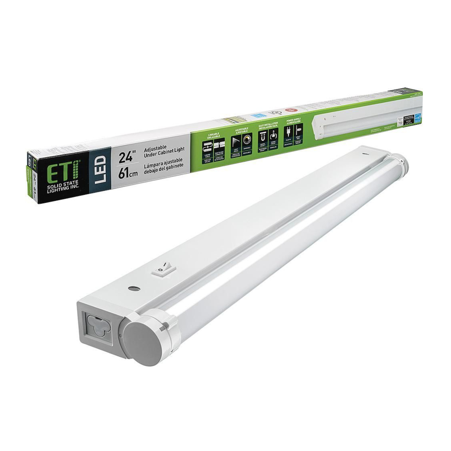
AdjUsTAblE lEd UNdER CAbINET lIGhT WITh GROW MOdE
NOTE: Keep your receipt and these instructions for proof of purchase.
WARNING: RISK OF ELECTRIC SHOCK. Ensure the electricity to the wires
you are working on is shut off. Either remove the fuse or turn off the circuit
breaker before removing an existing light fixture or installing the new one.
If you are unfamiliar with electrical installations, we recommend you contact
a qualified electrician to do the installation.
NOTE: Installing contractor is responsible for selecting a suitable location
that can support the weight of the fixture and determining the method for
mounting the fixture before installing, based on the type of ceiling.
Shut off power at the electrical panel before beginning the installation.
1
Remove existing fixture and set aside to recycle in accordance with local
2
requirements.
Installing contractor is responsible for ensuring required CCT is selected
3
during installation.
NOTICE: The factory setting for the correlated color temperature (CCT) is
2700K, which is the warmest white light.
Installing contractor is responsible for determining if the power is
4
supplied from the plug connector or if the fixture should be directly wired.
Suspension mounted fixtures cannot be directly wired.
NOTE: Do not use the linking cable or the plug adapter if directly wiring the
fixture.
surface MountIng
Screw
Back Plate
Knock out Holes
B
If using the plug connector, skip this step.
5a
If directly wiring the fixture:
• Unscrew the 4 screws to remove the back plate.
• Punch out one of the knock out holes on the back
plate.
If installing the MagnaMount™ mounting plate:
• Punch out the matching knock out hole on the
MagnaMount™ mounting plate.
Insert the strain relief clamp into the knock out hole
from the outside in on the back plate.
B
Back Plate
If using the plug connector, skip this step.
10a
If directly wiring the fixture, feed the wires from
the power supply through the strain relief clamp
in the back plate.
UsE ANd CARE GUIdE
Back Plate
A
If installing the MagnaMount™ mounting plate for
6a
installation, push a short mounting screw through one of
the screw holes on the MagnaMount™ mounting plate and
then through an O-Ring. Repeat with the remaining short
mounting screw.
If attaching to drywall instead of to the underside of a
7a
cabinet, drill pilot holes and tap in the drywall anchors at
the screw positions.
NOTE: Distance between 2 holes is 14.75in.
Wires
If using the plug connector, skip this step.
11a
If directly wiring the fixture:
NOTE: Make sure end cap is tightly in place before making
the electrical connections.
Make the electrical connections:
• Black wire to black wire.
• White wire to white wire.
• Green wire to ground wire.
Use wire connectors (not included) to cover the wire
connections and cover with electrical tape.
Tuck wires inside the fixture.
Reattach the back plate to the fixture.
Model # 53508101
Part # Gl-18IN-500lM-8-CP3-sV-Td
Package contents
Part
Description
A
Fixture
B
Strain Relief Clamp
C
O-Ring
D
Wire Clip
E
Mounting Screw (long)
F
Drywall Anchor
G
MagnaMount™
Mounting Plate
H
Plug Connector
I
14.5 in. Linking Cable
J
End-to-End Connector
K
Mounting Screw (short)
L
V-clip
Hardware not shown to actual size.
G
C
Wires
B
Back
Plate
Wire Connectors
Quantity
1
1
2
B
2
2
2
E
1
1
1
2
2
2
J
K
If using the plug connector or installing without the
8a
MagnaMount™ mounting plate, skip this step.
If directly wiring the fixture and installing the
MagnaMount™ mounting plate, feed the wires
through the MagnaMount™ mounting plate.
If installing the MagnaMount™ Mounting Plate,
9a
screw the MagnaMount™ mounting plate to the
underside of the cabinet or to the drywall and make
sure it is secure.
Certification # 53508101
A
C
D
F
G
H
I
L
K
G
K
C
Advertisement
Table of Contents

Related Manuals for ETI Solid State Lighting 53508101


Summary of Contents for ETI Solid State Lighting 53508101
- Page 1 Model # 53508101 Part # Gl-18IN-500lM-8-CP3-sV-Td Certification # 53508101 UsE ANd CARE GUIdE AdjUsTAblE lEd UNdER CAbINET lIGhT WITh GROW MOdE Package contents NOTE: Keep your receipt and these instructions for proof of purchase. WARNING: RISK OF ELECTRIC SHOCK. Ensure the electricity to the wires...
- Page 2 End Cap If installing using the MagnaMount™ mounting plate, place the fixture If direct wiring the fixture, skip this step. on the MagnaMount™ mounting plate and adjust the alignment as If using the plug connector, remove the end cap on the “Power In” end of the fixture and needed.
- Page 3 To prevent fire danger, do not run cord behind walls, ceilings, soffits, or cabinets where it may be inaccessible for examination. Cords should be visually examined periodically and immediately replaced when any damage is noted. • Maximum number of units to be interconnected: 53508101 (18 in.
- Page 4 N° modèle 53508101 N° de pièce Gl-18IN-500lM-8-CP3-sV-Td N° de certification 53508101 GUIdE d’UTIlIsATION ET d’ENTRETIEN lAMPE dEl sOUs ARMOIRE AjUsTAblE AVEC MOdE dE sERRE contenu De L’eMBaLLage REMARQUE : Gardez votre facture ainsi que ces instructions comme preuves d’achat. Pièce Désignation Quantité...
- Page 5 Capuchon d’embout Si vous installez la plaque de montage Magnamount , placez la lampe Si vous faites un câblage direct, sautez cette étape. sur la plaque de montage MagnaMount et ajustez-en l’alignement. Si vous utilisez l’adaptateur de fiche, enlevez le capuchon à l’extrémité « Power In » de la Si vous faites l’installation sans la plaque de montage MagnaMount lampe et connectez le câble d’interconnexion à...
- Page 6 être inspectés. Les fils doivent être inspectés visuellement de façon régulière et remplacez dès qu’un dommage est notee. • Nombre maximale d’unités interconnectées : 53508101 (lampe sous armoire de 45,7 cm) : 30 unités max. Distance maximale entre les unités interconnectées : 37 cm.
Need help?
Do you have a question about the 53508101 and is the answer not in the manual?
Questions and answers