Advertisement
Available languages
Available languages
Quick Links
nOTe: Keep your receipt and these
instructions for proof of purchase.
WarninG: Shut off the power at the
circuit breaker or fuse panel before
removing the old fixture, ballast, or
fluorescent tubes.
If you are unfamiliar with electrical
installations, we recommend you contact a
qualified electrician to do the installation.
INSTALLATION
nOTe: Installing contractor is responsible
for selecting a suitable location that can
support the weight of the fixture and
determining the method for mounting the
fixture before installing, based on the type
of ceiling.
Shut off power at the electrical panel
1
before beginning the installation.
Remove fixture and set aside to recycle
2
in accordance with local requirements.
Safety Rope
End Cap
Lens
A
Remove end trim from fixture by sliding it up.
3
Unlock lens at both ends of the fixture.
Lens swings open.
SurfAce MOuNTINg
Keyhole
Knock out hole
Lens
Hold the fixture to the desired ceiling location and
5a
mark the two keyholes (47in. apart). Punch out
the desired knock out hole that will be used for
wiring.
If mounting to drywall: Drill two 3/4in. holes in
6a
the ceiling. Fasten the toggle bolt into the butterfly
nut (not included) before inserting the flaps of the
toggle bolt into the ceiling, but do not fully tighten.
nOTe: Toggle bolts are only to be used for
mounting the fixture to plaster or drywall surfaces.
The installing contractor is responsible for
selecting the appropriate mounting hardware.
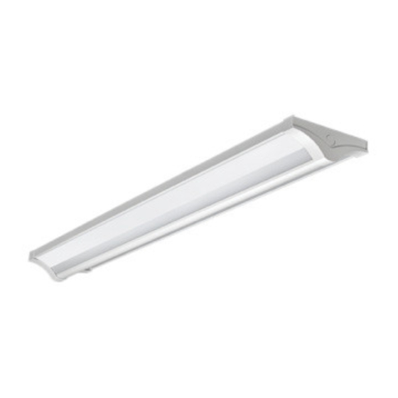
Use and Care GUide
direCT/indireCT WraP LiGHT
PAckAge cONTeNTS
Part Description
A
Fixture
B
Continuous Mounting Bracket
C
Toggle Bolt
D
Thumb Screws
E
Ring
F
Mounting Chain
G
V Clip Chain
H
Jumper Wire
I
Mounting Plate*
J
Mounting Screw*
K
Nut*
L
3/8" Conduit*
M
Hook*
N
Screws*
O
Plastic Drywall Anchor*
P
Stem Mounting Kit Screws*
Q
Stem Mounting Kit Nut*
R
Stem Mounting Kit Bracket*
S
Ceiling Plate*
T
Stem*
Hardware not shown to actual size.
* Accessory sold separately
Squeeze the tabs at both ends of the wire cover and
4
remove the wire cover.
Unplug the terminal ground wire from the fixture and the
wire cover.
A
Wire Connector
Lens
Insert the ring into the knock out hole and feed the
7a
wires from the fixture through the ring.
Make the electrical connections by inserting the wire
8a
into the respective wire connector:
• Black wire to black wire.
• White wire to white wire.
• Green wire to ground wire.
• If a 0-10v dimming circuit is available, connect
purple wire to purple wire and gray wire to gray
wire.
Tuck wires inside the electrical box.
Quantity
Accessory Model #
1
NA
1
NA
2
NA
2
NA
1
NA
2
NA
2
NA
5
NA
1
2
2
1
2
2
2
2
2
2
2
2
Lens
A
Terminal
Ground Wire
Wire Cover
A
E
Part # Wr-4FT-6700LM-8-40K-MV-LVd
Certification # 56567241
B
C
E
G
I
J
N
O
Q
R
T
C
A
Place the keyholes in the fixture around the toggle
9a
bolts in the ceiling and tighten the toggle bolts. Make
sure the fixture is secure.
Model # 56567241
A
D
F
H
K
L
M
P
S
C
Advertisement

Related Manuals for ETI Solid State Lighting 56567241


Summary of Contents for ETI Solid State Lighting 56567241
- Page 1 Model # 56567241 Part # Wr-4FT-6700LM-8-40K-MV-LVd Certification # 56567241 Use and Care GUide direCT/indireCT WraP LiGHT PAckAge cONTeNTS nOTe: Keep your receipt and these Part Description Quantity Accessory Model # instructions for proof of purchase. WarninG: Shut off the power at the...
-
Page 2: Suspension Mounting
End Cap End Cap Lens Lens Wire Cover Terminal Ground Wire Reconnect the terminal ground wire to the wire Close the lens cover. Move the locks to the lock position on both ends of cover. Reattach the wire cover to the fixture. the fixture. - Page 3 STeM MOuNTINg INSTALLATION This section is for suspended mounted fixtures only. Option Installation Accessory Kit Sold Separately Installing contractor is responsible for determining best installation method for desired location and selecting the appropriate mounting hardware. Punch out the 2 knock out holes on the fixture that will be used for stem mounting. Feed all the wires from the electrical box through the knock out hole.
- Page 4 56567241 n° de pièce Wr-4FT-6700LM-8-40K-MV-LVd n° de certification 56567241 GUide d’UTiLisaTiOn eT d’enTreTien LaMPe enVeLOPPanTe À ÉCLairaGe direCT/indireCT cONTeNu De L’eMBALLAge reMarQUe : Gardez votre facture Pièce Désignation Quantité N° d’accessoire ainsi que ces instructions comme preuves d’achat.
-
Page 5: Montage En Suspension
Capuchon d’embout Capuchon d’embout Diffuseur Diffuseur Couvre-fils Fil de terre Reconnectez le fil de terre au couvre-fils. Refernez le diffuseur. Poussez les loquets en position verrouillée à chaque Réattachez le couvre-fils à la lampe. extrémité de la lampe. Remettez les capuchons d’embout. Rétablissez le courant au panneau électrique. - Page 6 MONTAge Sur TIge Cette section ne s’applique qu’aux lampes suspendues. Nécessaire d’installation en option vendu séparément. Il en revient à l’installateur d’étblir la meilleure méthode de montage pour l’endroit voulu et de choisir la quincaillerie de montage appropriée. Faites sauter deux débouchures sur la lampe; elles serviront à la pose des tiges. Passez tous les fils de la boîte électrique à...
Need help?
Do you have a question about the 56567241 and is the answer not in the manual?
Questions and answers