Advertisement
Available languages
Available languages
Quick Links
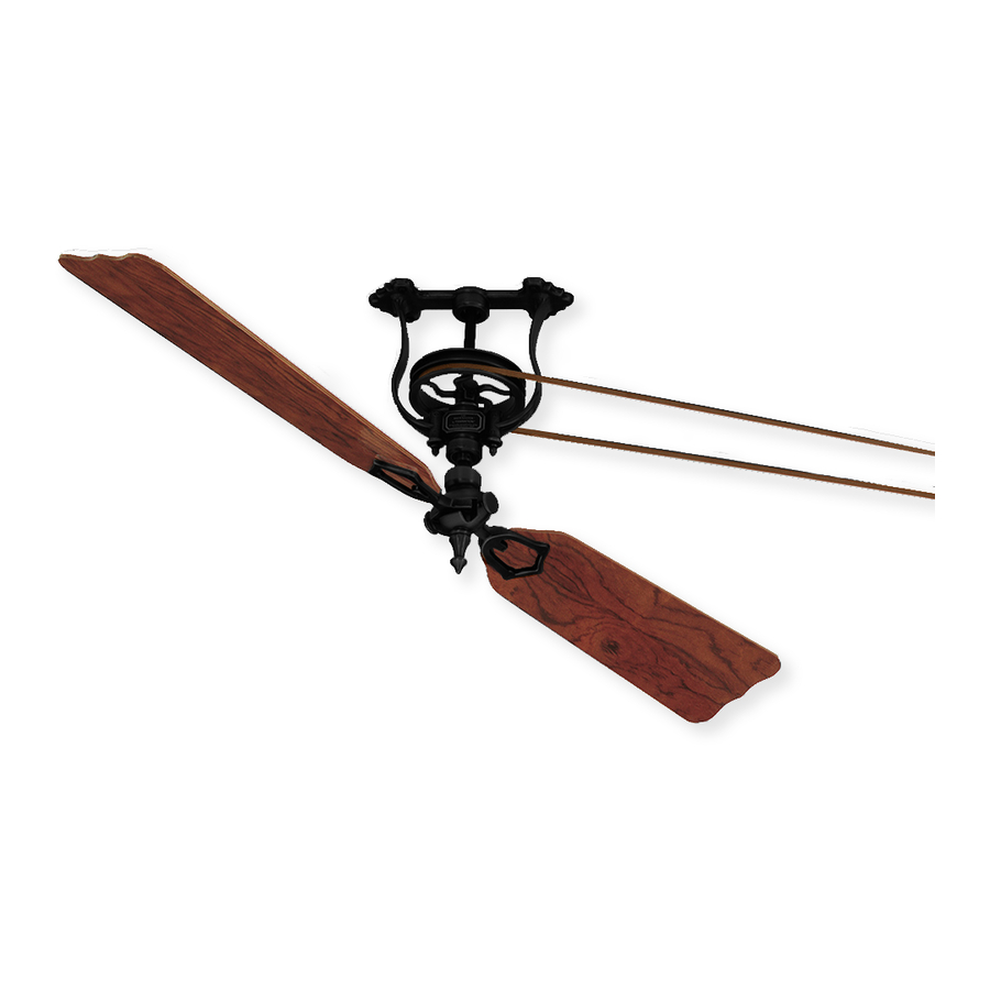
Long Neck FP20
Net Weight 15 lbs
(6.8 kg)
Support Directly From Building Structure
ATTACH YOUR RECEIPT HERE AND REGISTER YOUR FAN AT FANIMATION.COM
READ AND SAVE THESE INSTRUCTIONS
Date Code
For best and quick service please provide date code. You can find the date code on the Carton,
Wall Control, Frame of Fan and Motor Housing.
Questions, problems, missing parts? Before returning to your retailer, call our customer
service department at 1-888-567-2055, 8 a.m.-5 p.m., EST, Monday-Friday.
®
BREWMASTER
BELT-DRIVEN CEILING FAN
Short Neck FP10
Net Weight 11 lbs
(5.0 kg)
Purchase Date
MODEL #FP1280**-220
Español p. 18
Motor Assembly
Net Weight 15 lbs
(6.8 kg)
Advertisement

Subscribe to Our Youtube Channel
Related Manuals for Fanimation BREWMASTER FP1280-220


Summary of Contents for Fanimation BREWMASTER FP1280-220
- Page 1 Short Neck FP10 Net Weight 11 lbs (5.0 kg) Support Directly From Building Structure ATTACH YOUR RECEIPT HERE AND REGISTER YOUR FAN AT FANIMATION.COM READ AND SAVE THESE INSTRUCTIONS Date Code Purchase Date For best and quick service please provide date code. You can find the date code on the Carton, Wall Control, Frame of Fan and Motor Housing.
- Page 2 Important Safety Instructions WARNING: To avoid fire, shock and serious personal injury, follow these instructions. 1. Read your owner’s manual and safety information before installing your new fan. Review the accompanying assembly diagrams. 2. Before servicing or cleaning unit, switch power off at service panel and lock service panel disconnecting means to prevent power from being switched on accidentally.
-
Page 3: Table Of Contents
6. All costs of removal and reinstallation of the fan are the sole responsibility of the owner of the fan and not the store that sold the fan or Fanimation. 7. Fanimation reserves the right to modify or discontinue any product at any time and may substitute any part under this warranty. - Page 4 This manual is designed to make it as easy as possible for you , l l Tools Needed for Assembly Materials (Not Included) Wiring outlet box and box connectors must be of type re- • One Phillips head screwdriver • One stepladder quired by local code.
- Page 5 Unpacking Instructions and Parts Identification (continued) FP10 (Short)/FP20 (Long) Pulley Assembly and Hardware Parts Identification FP10 Wood Blade Holders FP20 Short Neck (for use with FP1022, FP1026, Short Neck Pulley FP1030 blade sets) (2) Pulley Assembly (1) Assembly (1) Traditional Blade Holders (for use with Palm, Bamboo, Wicker blade sets) (2) Belt (1)
-
Page 6: Electrical And Structural Requirements
Electrical and Structural Requirements Your new fan will require a grounded electrical supply line of 220-240 volts AC, 50 Hz circuit. The fan shall be Plywood (2 cm thick min.) mounted on a reliable surface, building structure, capable Backing Secured to Structural Member of supporting a load of at least 15.9 kg. -
Page 7: How To Hang And Wire Your Ceiling Fan
& Flat Fanimation. Substitution of parts or accessories not Washer designated for use with this product by Fanimation could (4 places) result in personal injury or property damage. Contact your retail store for missing or damaged parts. - Page 8 How to Hang and Wire Your Ceiling Fan (continued) ▲WARNING Mount retainer to junction box with screws (provided with your junction box). (Figure ) Loosen strain relief and pull excess lead wires through canopy. Re-tighten strain relief. Cut and strip lead wires. ▲WARNING 220-240 VAC SUPPLY (User Supplied)
- Page 9 How to Hang and Wire Your Ceiling Fan (continued) After the connections have been made, tighten the lag bolts to secure fan base assembly to the ceiling, making sure that the electrical wires are completely inside the base assembly and not pinched between the base and the ceiling.
-
Page 10: Belt Splicing Instructions
Belt Splicing Instructions Wrap the belting around the two pulleys that will be connected and overlap the belting as shown. Use the spring clamps provided to hold the belting in place temporarily. With the clamps remaining in the same place, grasp both ends of the belting and pull tight. The clamps should hold the belting together after releasing the belt. -
Page 11: Mounting The Fan Blades
Mounting the Fan Blades CAUTION Lay side “A” of the blade holder on a fl at surface with the inside of the blade holder facing up. This is the side with the threaded posts and pitched foot (Figure 1). Position the palm leaf, or the woven bamboo or wicker blade over the blade holder with the threaded posts showing. -
Page 12: Operating Your C3-220 Wall Control
Operate Your C3-220 Wall Control Restore electrical power and operate your fan by rotating the control knob to desired setting (Figure 1): Position – low fan speed Position – medium fan speed Position – high fan speed Maintenance Periodic cleaning of your new ceiling fan is the only CAUTION maintenance that is needed. -
Page 13: Troubleshooting
Troubleshooting WARNING Trouble Probable Cause Suggested Remedy Fuse or circuit breaker blown. Check main and branch circuit fuses or circuit breakers. Loose power line connections to the fan, or loose Check line wire connections to fan and switch wire switch wire connections in the switch housing. connections in the switch housings. - Page 14 The Brewmaster Motor FP1280**-220 ® Exploded-View Parts List Brewmaster Motor Assembly FMA1280**-220 Switch Cap Assembly AP3247** Wiring Harness AP128099**-220 Flat Washer Switch Cap Base Motor Pulley Set Screw 5/16-18 x 3/8 W/Locktite Motor Housing P106** M/S, Washer Hd, , Black Motor Assembly Hex Nut, -24 x 4mm (4)
- Page 15 Parts List Ref # Description Part # Pulley Assembly FP10** /FP20** Pulley with set screw Short Frame (Short model) Long Frame (Long model) Cushion, Bearing, Black Bearing Shaft Blade Holder (2) (Wooden Blades only) P1212** ,Black (5) HDWFP10HB** Bag, Lag Bolt, , Black, w/washers (4) HDWFP10LG Bag, Wood Blade Screw,...
- Page 16 The Brewmaster Pulley Assembly Pack ® FP10__ / FP20__ (Short) (Long) Exploded-View The illustration shown is not to scale or its actual configuration may vary.
- Page 17 10983 Bennett Parkway Zionsville, IN 46077 Phone: 888-567-2055 Outside U.S.: 317-733-4113 FAX: 866-482-5215 2020/10 V.01 FANIMATION.COM Copyright 2020 Fanimation...
- Page 18 Conjunto del motor Peso neto 6.8 kg (15 lb) Cuello corto FP10 Peso neto 5.0 kg (11 lb) ADJUNTE SU RECIBO AQUÍ Y REGISTRE SU VENTILADOR EN FANIMATION.COM LEA Y GUARDE ESTAS INSTRUCCIONES Código de fecha Fecha de compra Para ofrecer un servicio rápido y de calidad, por favor suministre el código de fecha. Puede encontrar el código de fecha en el paquete, Control de pared, marco del ventilador o en la carcasa...
- Page 19 GARANTÍA LIMITADA DE POR VIDA DEL MOTOR - Si se produjera una falla en alguna de las partes del motor de su ventilador debido a un defecto en los materiales o en la fabricación durante el tiempo de vida del comprador original, Fanimation proporcionará la pieza de repuesto sin cargo una vez que el ventilador defectuoso sea devuelto a nuestro centro de servicios nacional.
- Page 20 Materiales Herramientas necesarias para el ensamblaje (No incluido) La caja de distribución eléctrica y los conectores de la caja deben ser del tipo • Destornillador Phillips • Pelacables requerido por el código local. El cable más pequeño debe ser un cable de tres conductores (de dos conductores con conexión a tierra) del siguiente tamaño: •...
- Page 21 Instrucciones para el desempaque (cont.) Unidad de polea FP10 (Corta)/FP20 (Larga) e identificación de las piezas del equipo Unidad de la Soportes de pala de madera Unidad de la polea de cuello (para su uso con los sets de polea de cuello corto FP10 (1) palas FP1022, FP1026, FP1030) (2) largo FP20 (1)
- Page 22 Requisitos eléctricos y estructurales Su nuevo ventilador de techo requiere una línea de suministro eléctrico con conexión a tierra de 220-240 voltios de CA, de 50 Hz. NOTA LA INSTALACIÓN Si el ventilador reemplazará a una lámpara existente, desconecte la electricidad de la caja de fusibles principal y retire la lámpara.
- Page 23 Instalación y cableado del ventilador de techo NOTA LA INSTALACIÓN ADVERTENCIA NOTA LA INSTALACIÓN 1. En primer lugar, taladre los orificios guías de 3/16˝ en la base de contrachapado o viga de sujeción para evitar que se raje o rompa. Instale la unidad de la polea en el techo con los 4 tirafondos y las arandelas planas.
- Page 24 Instalación y cableado del ventilador de techo (Cont.) ▲ ADVERTENCIA Monte la retención para la caja de empalme con los tornillos (suministrados con la caja de empalme). (Figura 3) Afloje el relevador de tensión y tire de los cables que sobren a través de la cubierta.
- Page 25 Instalación y cableado del ventilador de techo (Cont.) Después de las conexiones se han hecho, apriete los pernos de fijación para asegurar el conjunto de seguidores de base hasta el techo, asegurándose de que los cables eléctricos estén completamente dentro de la unidad de la base y no quede atrapada entre la base y el techo.
- Page 26 Instrucciones del ensamblaje de la correa Figura 3 Figura 4 Figura 5 Figura 1 Figura 6 Figura 2 Figura 7...
- Page 27 Montaje de las palas del ventilador PRECAUCIÓN Apoye el lado liso del soporte de aspas sobre una superficie plana, con la parte interior del soporte mirando hacia arriba. Este es el lado que tiene los pilotes roscados y la base inclinada. (Figura 1).
- Page 28 Instrucciones de funcionamiento: control de pared C3-220 Vuelva a conectar la corriente eléctrica en la caja de distribución eléctrica mediante la conexión de la electricidad en la caja de fusibles principal (Figure 1): • 3 Interruptor deslizable = low speed •...
- Page 29 Solución de problemas ▲ ADVERTENCIA Problema Causa posible Solución sugerida Revise los fusibles del circuito principal y derivado o El fusible o el disyuntor están fundidos. los disyuntores. Las conexiones eléctricas del ventilador o del Revise las conexiones eléctricas del ventilador y del interruptor en la caja del interruptor están flojas.
- Page 30 The Brewmaster Motor Pack FP1280**-220 ® Despiece Lista de piezas N.º de ref. Descripción Pieza N.º Unidad del motor Brewmaster FMA1280**-220 Unidad de la carcasa del interruptor AP3247** Mazo de cables AP128099**-220 Tuercas Arandelas planas Base de la carcasa del interruptor Polea del motor Tornillo de fijación de 5/16-18 x 3/8 con Loctite P106**...
- Page 31 Lista de piezas Unidad de la polea FP10** /FP20** Polea con tornillo de presión Marco corto (modelo corto) Marco largo (modelo largo) Funda, rodamiento, negro Rodamiento Centro Soporte de pala (2) (Solo de palas de madera) P1212** Bolsa, Tornillos de Soporte a Centro, 10-32 x ½˝, ˝...
- Page 32 El pack de montaje de la polea Brewmaster® FP10__ (Corto) / FP20__ (Largo) Despiece la ilustración que se muestra no está hecha a escala y su configuración real puede variar.
- Page 33 10983 Bennett Parkway Zionsville, IN 46077 Llame sin cargo al (888) 567-2055 FAX (866) 482-5215 Desde fuera de los EE.UU., llame al (317) 733-4113 2020/10 V.01 Visite nuestro sitio Web en www.fanimation.com Copyright 2020 Fanimation...
Need help?
Do you have a question about the BREWMASTER FP1280-220 and is the answer not in the manual?
Questions and answers