Table of Contents
Advertisement
Quick Links
Advertisement
Table of Contents

Subscribe to Our Youtube Channel
Related Manuals for VMI VIBER X4


Summary of Contents for VMI VIBER X4
- Page 1 MART PRODUCTS FOR SMART PEOPLE VIBER X4™...
- Page 2 Vibration Measurement Instruments...
- Page 3 Email: info@vmiab.com www.vmiab.com Copyright© 2020 by VMI International AB. No copying or reproduction of this information may be un- dertaken without written permission of VMI International AB. Due to continuous product development the information in this document may be changed without further notice.
-
Page 4: Table Of Contents
Vibration Measurement Instruments Table of Contents Instrument basics Connectors and sensors on front and rear Main menu description Instrument settings General settings Transducers Select sensor, Update, Firmware, Pictures, Fonts Language, Licenses, Factory reset, System information Connection, Files Exporting data in file menu Route Measuring in Route Instrument Route Manager... -
Page 5: Instrument Basics
Vibration Measurement Instruments Instrument basics This section contains basic information about how to operate the instrument and the meanings of the differ- ent keys and symbols. ON/OFF Used to switch the instrument ON and OFF. OK (Enter) Used to start a measurement, resume the measurement from Hold status, confirm an action or go forward in a menu. -
Page 6: Connectors And Sensors On Front And Rear
From the left in the picture: USB-C connector: Used to connect the VIBER X4™ to a PC to transfer files or to connect to a battery charger. Audio connector: Used to connect a headphones connector with a stereo 3.5mm plug. -
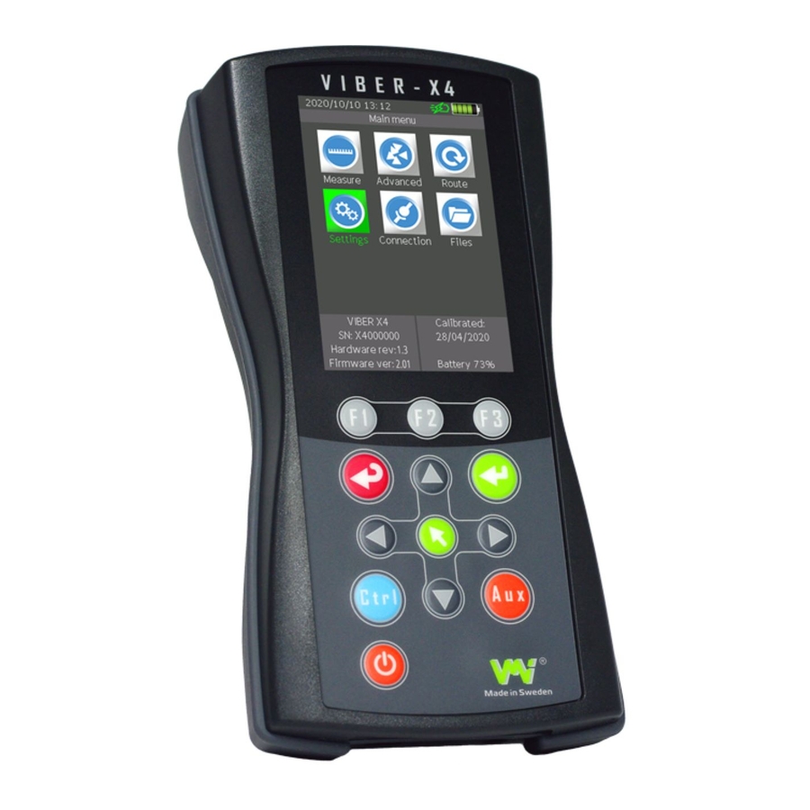
Page 7: Main Menu Description
• Mute. Shown when mute is enabled while using audio. • Quick charger. Shown when charging with the original VMI quick charger. • Charger. Shown when using common chargers with a 5V output. • Battery. Each segment in the picture corresponds to 20% battery capacity. -
Page 8: Instrument Settings
Vibration Measurement Instruments Instrument settings • Tools. Check the instrument functions. • General. Set the general instrument parameters. • Transducers. Edit the used transducer. • Select Sensor. Choose which transducer is to be used. • Update. Update the instrument firmware and applications. •... - Page 9 Vibration Measurement Instruments Tools This menu contains various tools for checking the functionality of the keypad, the display and Bias measurement. Keypad This tool performs a keypad test. Every time you press a key, the key name and the corresponding key code will be shown. Press ESC to exit the test. Display This tool performs a color display test.
-
Page 10: General Settings
Vibration Measurement Instruments General settings Use the arrows and the OK key to change and save values. • Set date Set the date, which is also used whenever data is stored. • Set clock Set the clock, which is also used whenever data is stored. •... -
Page 11: Transducers
Vibration Measurement Instruments Transducers In this menu, you can edit a list of sixteen transducers which can be used for the measurements. The first three positions are prepared for accelerometer, velocity and displacement sensors. • Name Transducer description [max 15 characters]. This will appear whenever the pro- gram displays transducer characteristics or asks for transducer selection. -
Page 12: Select Sensor, Update, Firmware, Pictures, Fonts
Vibration Measurement Instruments Select sensor This menu contains configuration settings for Vib1 and tachometer inputs. The settings will apply to all measurements. In most measurement settings, this menu is accessible by the Function key F1. Tacho Idle This setting is to configure when the tachometer will trigger each rota- tion. -
Page 13: Language, Licenses, Factory Reset, System Information
Vibration Measurement Instruments Language This updates the instrument’s language. The instrument’s default language is English but other languages can be easily installed using this feature and changes in the general settings menu. Select the desired language file from the list if you have more than one file and press OK to start updating. -
Page 14: Connection, Files
Vibration Measurement Instruments Connection This maintains communication between the instrument and the PC via a USB port. Connect the instrument to a PC with a USB-C cable, start the instrument and go to the connection menu. “Connected” appears on the display when communication is active. -
Page 15: Exporting Data In File Menu
It is possible to export saved data in a different format. This allows you to use saved measurement results from Viber X4 in a third-party software. Spectrum and envelope files can be exported from MV1 format to CSV format and waveform files can be exported to WAV or TXT format. -
Page 16: Route
2. Indirectly in SpectraPro® by transferring the Route to a file and then copying the file to the Route folder in the VIBER X4™ memory card. If you copy the Route file to another folder or to the memory card root directory, the instrument will not show the file in the existing Route list. -
Page 17: Measuring In Route
Vibration Measurement Instruments Measuring in Route When entering the Route menu, you enter the location of the last point selected in the most recently used Route file. This means that when you stop the measurements in a Route, you can shut down the VIBER X4™... -
Page 18: Instrument Route Manager
Vibration Measurement Instruments Instrument Route Manager Enter the Route manager to select another Route or see the details of a Route. You can select a Route loaded in the instrument. Use the arrow keys and press OK. Using the function keys you can also: •... -
Page 19: Getting Started With Measurements
Vibration Measurement Instruments Getting started with Measurements The general procedure for measurements using VIBER X4™ can be divided into 4 steps: 1. Parameter check: When pressing OK, the instrument will check if the transducers meet the required conditions and start the data acquisition for the measurement. In the meantime, the instrument will display a diagram related to the stability of the input signal and, for some measurements, auto ranging will ask you to confirm the stability of the signal. - Page 20 Vibration Measurement Instruments General Measurement Settings In this section, the general application settings that are most commonly used by different applications are described. The settings can vary from application to application but their function is the same. Measurement type Millivolt, Acceleration, Velocity or Displacement. Depending on the choice, the instrument will integrate and display the units of measurement differently.
- Page 21 Vibration Measurement Instruments Window (Hanning, Hamming, Blackman, Kaiser-Bessel, Rectangular) Windowing is used to shape the time portion of your measurement data in order to minimize edge effects that can result in spectral leakage in the FFT spectrum. The spectral resolution of your frequency result will increase if Window is used correctly.
- Page 22 Vibration Measurement Instruments Hanning This is useful for measurements where better frequency resolution than some of the other windows is desired but where moderate side lobes do not present a problem (reso- lution is more important than amplitude accuracy). Hamming This window is optimized to minimize the maximum (nearest) side lobe, giving it a height of about one fifth that of the Hanning window.
- Page 23 Vibration Measurement Instruments Averaging (Linear, Exponential, Smart, Peak Hold) Averaging means that the different parts are averaged together and can then be used for reducing random errors, such as background vibration due to a source other than the machine being measured. Linear means that each part spectra/value has the same weight in the final spectra/value.
- Page 24 Vibration Measurement Instruments Frequency unit (Hz or CPM) With this setting you select which frequency unit is displayed, either Hertz (Hz) or Counts per Minute (CPM). Save Waveform with spectra If enabled, the analysis file will also contain waveform data. Speed Measurement Measures speed along with the measurement.
-
Page 25: Recommended Vibration Levels
Vibration Measurement Instruments Recommended Vibration Levels This chapter describes the ISO standard 10816-3 and the recommended vibration levels. It also describes resonance and where to place the transducers for best result. The lists and tables in this chapter can be used as a first consideration when you approach a machine that is newly commissioned, or after some time in operation. -
Page 26: Iso Standard 10816-3
Vibration Measurement Instruments ISO standard 10816-3 The ISO standard 10816-3 classifies machines differently according to whether the machines are considered to be flexibly or rigidly mounted. This reflects the location of the machines stiff body resonances related to the basic running speed of the machine. For instance, a machine supported by rubber or spring has resonances at low running speeds. -
Page 27: Measure (Off Route)
Vibration Measurement Instruments Measure (Off Route) This section describes the applications in the Measurements menu. In this menu the programs are used to make an analysis on site or when you need to make additional measurements during Route. The following measurement applications are included in the instrument when delivered. See the specified application section for a detailed description. - Page 28 Vibration Measurement Instruments Phase In the Phase application you can measure the Amplitude and Phase of the vibration using 1 or 2 vibration sensors and a speed sensor. This tool will help you to confirm a specific machine fault or prevent false con- clusions.
-
Page 29: Total Value
Vibration Measurement Instruments Measure Total Value The Total Value screen for vibration measurement is shown at the top. A bar on the right of the value indicates the measurement stability. The lower the bar, the more stable. On the lower part of the screen there are details regarding: •... -
Page 30: Spectra
Vibration Measurement Instruments Spectra This measurement displays a spectrum (chart) of the frequencies at which the machine component is vibrating and the amplitude of the vibration at each of these frequencies. Measure Spectra There are three windows at the top of the screen. The left win- dow shows the amplitude of the cursor, the middle window shows the frequency of cursor and the right window shows the total value. - Page 31 Vibration Measurement Instruments Aux It is possible to freeze (HOLD) the measurements by pressing the Aux key. Menu In HOLD mode, the (MENU) key menu can be accessed where it is possible to: • Change the Main cursor • Free The cursor is positioned over a line of the screen. If the screen area is less than the number of lines, the cursor moves pixel by pixel on the screen and displays the values for the highest line represented on the pixel.
- Page 32 Vibration Measurement Instruments • Highest peak list Shows a list containing the 20 highest peaks in spectrum measurement. The list is sorted with the highest peak first and allows a quick overview of the 20 highest peaks and the possibility to move the cursor directly to the selected peak in spectrum menu. By selecting one of the peaks in the list and pressing OK, you return to the spectrum menu with the cursor over the peak you have selected in the list.
- Page 33 Vibration Measurement Instruments • Save Saves a measured spectrum file in the SD memory card. It can be opened later in file menu or transferred to PC software to be analyzed. Spectra Measurement Settings When measuring a spectrum, you can enter the settings menu by clicking F3.
-
Page 34: Bearing Condition
Vibration Measurement Instruments Bearing Condition The bearing condition value is a sum average value, the RMS value, of all high frequency vibrations in the set frequency interval. This value is an acceleration average with the unit “ g ”. Interpretation of the Bearing Condition Value The bearing condition value is an indirect method of measuring the status of anti-friction bearings. - Page 35 Vibration Measurement Instruments Measuring Bearing Condition The value of the BC measurement is shown at the top. A bar on the right of the value indicates the measurement stability. On the lower part of the screen there are details regarding: •...
-
Page 36: Envelope
Vibration Measurement Instruments Envelope Envelope is a spectrum measurement that enhances the energy in the high frequency signals and is used to find early signs of bearing faults. Envelope can also be used to detect cavitation in pumps. When you want to see the fluctuations of high frequencies it is better to use the unit “g”... - Page 37 Vibration Measurement Instruments Aux You can freeze (HOLD) the measurements by pressing the Aux key. Menu In HOLD mode, you can access the (MENU) key menu where you can: • Change the Main cursor • Free The cursor is positioned over a line of the screen. If the screen area is less than the number of lines, the cursor moves pixel by pixel on the screen and displays the values for the highest line represented on the pixel.
- Page 38 Vibration Measurement Instruments Envelope Measurement Settings When measuring envelope, you can enter the settings menu by clicking F3. The instrument will display the settings menu where the following parameters can be set: • Detection type RMS, Peak or Peak-Peak • Frequency Range Hz 600-1200, 1200-2200, 2200-3200, 3200-4200 and 3200-20000 Hz •...
-
Page 39: Phase
Vibration Measurement Instruments Phase In the Phase menu you can measure Amplitude & Phase using a vibration sensor and a speed sensor. The Phase application can help you diagnose machine faults such as, for example, resonance, misalignment, looseness and soft foot. The Phase application can also help you separate faults that at first look like unbalance but in reality are caused by something else (for example misalignment). -
Page 40: Speed
Vibration Measurement Instruments Speed The speed (machine revolution) can be measured with an Ex- ternal Tachometer. In the speed menu, all system resources are used only for speed measurement to get the best performance, this means that the accuracy and limits of the speed are ex- tremely high. -
Page 41: Temperature
Vibration Measurement Instruments Temperature In the Temperature menu you can, for example, measure the bearing housing tem- perature (or any other surface temperature) with the built-in infrared temperature sensor. Emissivity Set the coefficient for surface reflection factor (Emissivity factor) using a check via a contact probe (the table with emissivity factors is also included in the instru- ment’s context sensitive help menu). -
Page 42: Audio
Vibration Measurement Instruments Audio Listening to bearing noise is an established, proven method. Sound analyses of low speed bearings and gears can sometimes be much faster and even more reliable than BC value. This is also a good technique for estimating lubrication volume. NOTE The audio connector must be a 3.5mm stereo plug. -
Page 43: Balancing
Vibration Measurement Instruments Aadvanced measurements This section contains features that are not included in the standard version of Viber X4™ and ones that require licenses. Contact one of VMI’s authorized dealers close to your location to purchase licenses. Balancing Balancing is a procedure by which the mass distribution of a rotor is adjusted to ensure that the vibration and/or forces on the bearings at a frequency correspond- ing to service speed are within specified limits. - Page 44 Vibration Measurement Instruments Speed tolerance The tolerance of the current balancing speed is compared with the saved balancing speed to consider wheth- er the measurement is suitable for the balancing procedure. When the measured speed is outside of this tol- erance, the speed value will be shown in yellow.
- Page 45 Vibration Measurement Instruments ISO 1940 Balance Quality Grades In ISO1940 machines are divided into different grades called Quality Grades NOTE ISO 1940 Quality Grades is only an overview and not an extraction from the standard. G 0.4 Gyroscopes, Spindles, discs and armatures of precision grinders. G 1 Record players, Grinding-machine drives, Small electric armatures with special requirements.
- Page 46 Vibration Measurement Instruments Balancing steps There are 3 basic steps to performing a new balancing session: 1. Initial Run After you have made the settings for the balancing session, the rotor must be run at the balancing speed. When the speed is stabilized: •...
- Page 47 Vibration Measurement Instruments • Keep trial weight after run In this case the instrument will calculate a balancing weight that will balance both the trial weight and the original unbalance at the same time. Why do I want to keep the trial weight in the machine? •...
- Page 48 Response matrix VIBER X4™ calculates and stores the unbalance sensitivity called Response Matrix while you are balancing. Next time you want to balance the same ma- chine, you can use the Response Matrix and the instrument calculates the balanc- ing weights directly after the first trial run, or if all the transducers are already mounted, even while the machine is still in production.
-
Page 49: Waveform
Vibration Measurement Instruments Waveform The waveform is the shape of a time domain signal as seen on an oscilloscope screen. It is a visual represen- tation or graph of the instantaneous value of the signal plotted against time. Inspection of the waveform can sometimes reveal information about the signal that the spectrum of the signal does not show. - Page 50 Vibration Measurement Instruments Waveform measurement When entering the waveform measurement, after the settings menu, a time domain signal window is shown in the middle of the display with some values shown above. On the top left of the screen, the amplitude value of the blue cursor is shown, in the middle, the amplitude value of the green cursor is shown and on the right, the frequency calculat- ed between these two cursors can be seen.
-
Page 51: Charging
VIBER X4™ uses the latest battery charging technology called QC 3.0. We recommend using the VMI’s original charger which is supplied with the VIBER X4™ on delivery. It is also possible to use an AC/DC adapter with 5V DC/2A output but this extends the charging time. When the charger is connected to VIBER X4™, the charging process starts automatically, regardless of whether the VIBER X4™... -
Page 52: Battery
Vibration Measurement Instruments VMI’s original quick charger VMI’s charger is a quick charger with QC 3.0 technology. Quick Charge 3.0 is engineered to refuel devices up to four times faster than conventional charging. The charger is supplied with EU/US and UK Plugs and a USB-C cable. -
Page 53: Supplied Items
Vibration Measurement Instruments Supplied items Standard VIBER X4™ • 1 pc. VIBER X4™ • 1 pc. High performance accelerometer • 1 pc. Transducer cable (1 m) • 1 pc. Battery charger with EU/US and UK Plugs • 1 pc. USB-C cable for transfer data to PC and charging •... -
Page 54: Demo Unit
Vibration Measurement Instruments Demo unit These units may only be owned by VMI’s authorized resellers and may not be resold to end users. They are not included in VMI’s standard service program and are not covered by any warranty repairs or calibrations. -
Page 55: Important Information
VMI takes no responsibility for any accidents to people and machines. VMI and our authorized dealers will take no responsibility for any damage to machines and plants as a result of using the VIBER X4™ measurements. -
Page 56: Technical Data
Vibration Measurement Instruments Technical data 24 bit, 128 kSPS Dynamic range 120 dB Memory 32 GB 3.5 inch Amorphous TFT-LCD Size & Resolution 320 x 480 pixels Colors 65536 All standard ICP accelerometers (4mA/24V), velo- AC inputs cimeters or general purpose AC transducers Tacho input 0.5 to 24 V Peak-Peak Temperature... -
Page 57: Declaration Of Conformity
Warranty claimed products shall be returned prepaid to VMI for service. We reserve the right to repair or to replace defective products. Always try to explain the nature of any service problem by e-mail or telephone. First check all naturally occurring problems, such as discharged batteries, broken cables, etc.
Need help?
Do you have a question about the VIBER X4 and is the answer not in the manual?
Questions and answers