
Related Manuals for VMI VIBER-A


Summary of Contents for VMI VIBER-A
- Page 1 VIBER-A Manual Authorised distributo VMI AB Torsgatan 1 S-603 63 Norrköping, Sweden Tel. 011-311667 / 311668 Fax. 011-311678 e-mail: vmiab@telia.com www.vmi-instrument.se...
- Page 2 Page 2...
- Page 3 Warranty disclaimer VMI AB warrants the products to be free from defects in material and workmanship under normal use and service within two years from the date of purchase and which from our examination shall disclose to our reasonable satisfaction to be defective.
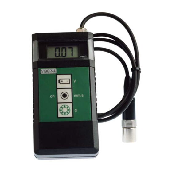
- Page 4 Functions Start of the instrument Press this symbol key and the instrument starts to measure. The instrument will be shut off automatically after approximately 2,5 minutes. Battery check Press this symbol key and keep it pressed and the instrument shows the battery voltage. Change the battery when the voltage is below 7 volts.
- Page 5 How to make good measurements. The sensitivity direction of the transducer coincides with the centre axis of the transducer. The transducer end (with the M6 stud) is pushed firmly against the measurement point. The main purpose is to make the complete transducer to fully participate in the motion of the measurement point.
- Page 6 The VIBER-A is mainly intended for measurements against the housing and bearings of machinery according to the intentions of the standards. You can also use it to measure other parts such as piping, valves, etc. Note that in some cases the mass of the transducer may influence the reading.
- Page 7 The ISO standard is classifying the machines differently if the machines are considered as flexible or rigid mounted. This reflects the location of the machines stiff-body resonance’s related to the basic running speed of the machine. For instance, a machine supported by rubber or springs often have resonance’s at low running speeds.
- Page 8 Modern machines have high rpm´s and flexible bearing-supports and foundations and can be treated as flexible even when it is not mounted on rubber or springs. The ISO 10816-3 standard allows for slightly higher limits when a foundation is considered flexible than when if it is rigid. A conclusion from this is also that a resonant condition in principle is not allowed or at least should be avoided at operating speeds.
- Page 9 Recommended vibration levels in mm/s an common findings. The following is in part an extraction of the old standard ISO 2372 class 4, large machines on flexible foundations, with some common findings added. This simplified list can be used, as a first consideration, when you approach a machine newly commissioned or after some time in operation.
- Page 10 Resonance When working with vibrations in machine maintenance, you will soon find that resonance is a common but rather unknown problem in modern machinery. To understand a resonance you can compare with the string of a guitar. The string has its natural basic tune that will ring as soon as the string is struck.
- Page 11 To identify the presence of a resonance, measure the vibration levels in three perpendicular directions at the bearings. If you find a measurement with at least three times higher level than in the other directions you should consider a resonance a likely possibility. The resonance is amplifying the mechanical force and thus gives a high vibration in that direction.
- Page 12 Press the green bearing symbol, keep it pressed and the instrument measures the bearing condition value . The bearing condition value is RMS value of all high frequency vibrations in the range of 3.200 Hz to 20.000 Hz. This average has the unit g (= acceleration due to gravity) Bearing condition value with unit “g”...
- Page 13 What is a bearing condition value? The bearing condition value in Viber-A is the sum average value, RMS value, of all high frequency vibrations between 3200 Hz to 20000 Hz. This value is an acceleration average with the unit "g" because high frequencies give a large signal if it is measured in acceleration.
- Page 14 Balancing with VIBER-A It is only possible to balance machines where the unbalance is the major cause of vibration. Do not change the position of the vibration transducer after the start of the balancing procedure. Balancing using this method requires only three consecutive trial runs and changing the balance status of the rotor.
-
Page 15: Trial Run
This is the procedure for the TWO-POINT BALANCING METHOD: TRIAL RUN 1: Select the running speed and choose the measuring point. Measure and note the vibration level and stop the machine. Note this vibration reading A. TRIAL RUN 2: Put in a trial weight in the balancing plane. - Page 16 CALCULATION We now have all the necessary machine information to start the calculations. Compare the vibration levels reading 2 reading 3. Call the highest of reading 2 reading 3 and the smallest for C. Draw a figure where you use a length measure proportional to the actual vibration level measured on each reading A, respectively.
- Page 17 THE SIZE OF THE BALANCING WEIGHT The SIZE of the balancing weight that you should put on the balancing plane is proportional to the size of the trial weight with the same relation as the line in the figure. In other words: trial weight * the length of Balancing weight...
- Page 18 MISCELLANEOUS If you prefer to calculate the balancing weight, this is the formula: TROUBLE HINTS The most difficult task in balancing is to guess a suitable size of the trial weight because we do not know the unbalance sensitivity of the machine.
- Page 19 BALANCING USING THE THREE-POINT METHOD. The three point method gives you the size and the location angle (a) without guessing the position of the balancing weight. Be sure to choose the same speed during all trial runs and the same radius for all trial weights and the balancing weight.
- Page 20 Step 4. Move the trial weight to position B. Start the rotor and measure the vibration level R3. In our example = 10mm/s. Draw a circle proportional to with the centre in position B. Step 5. Move the trial weight to position C.
- Page 21 Step 6. All the three circles intersect in a common point D. Draw a line from the centre of the circle to the point D. Call this line R5. Measure the length of this line using the same scale as before. In our example = 6.5 and it is the vibration level...
- Page 22 If in our example the trial weight = 87 grams then the balancing weight will be: 87 * 8 BW = ------------- = 107 grammes Use a protractor to measure the angle between and A. This angle is also the angular position of the balance weight relative to positon in the rotor.
- Page 23 TECHNICAL SPECIFICATIONS VIBER-A INPUT SENSITIVITY: 100mV/g calibrated at 156,15 Hz. MEASURING RANGE: Velocity: 0-200 mm/s RMS FREQUENCY RANGE: Total level 10-3200Hz, options : 2-3200Hz, 10-1000Hz Bearing condition 3200Hz - 20000Hz The measurement mainly follows ISO 2954, to conform with the new vibration standard ISO10816-3.
Need help?
Do you have a question about the VIBER-A and is the answer not in the manual?
Questions and answers