
Related Manuals for YOKOGAWA SC72


Summary of Contents for YOKOGAWA SC72
- Page 1 User’s Manual Model SC72 Personal Conductivity Meter IM 12D03D02-01E IM 12D03D02-01E 4th Edition...
- Page 2 Preface Preface Thank you for purchasing the Model SC72 Personal Conductivity Meter. Please read this manual thoroughly before using the meter. The related documents (User's Manual) are as follows. IM 12D03D02-01E Model SC72 Personal Conductivity Meter (this manual) IM 12D03D02-02E Model SC72 Personal Conductivity Meter Quick Manual * the “E”...
- Page 3 Preface Liquid Crystal Display (LCD) Characters On the LCD alphanumeric characters are displayed as follows. Alphabet Display Alphabet Display Numerals Display All display segments F00.ai Note Regarding Panels Shown in this Manual: Panels shown in this manual should be regarded as examples. Actual panel format may vary depending on parameter settings and on type of connected sensor.
- Page 4 In addition, performance deterioration of the sensor caused by the operating environment mentioned above is not considered to be a defect. Yokogawa cannot carry out repairs in such a case so please replace the sensor.
- Page 5 Do not dispose in domestic household waste. When disposing products in the EU, contact your local Yokogawa Europe B. V. office. Authorised Representative in EEA The Authorised Representative for this product in EEA is Yokogawa Europe B.V. (Euroweg 2, 3825 HD Amersfoort, The Netherlands). IM 12D03D02-01E...
-
Page 6: Table Of Contents
1.1 Features .......................... 1-1 1.2 Specifications ........................1-2 1.3 When You Receive This Conductivity Meter ..............1-4 1.4 Contents of Model SC72 Personal Conductivity Meter Package .............. 1-5 1.5 Component Names and Functions ................. 1-6 1.6 Sensor Part Names and Functions ................. 1-7 1.7 Options (Available Separately) .................. - Page 7 Contents Toc-2 IM 12D03D02-01E...
-
Page 8: Outline
1. Outline 1. Outline The Model SC72 Personal Conductivity Meter is an accurate, portable, easy-to-use conductivity meter. It includes not only self-diagnostic functions, to help ensure validity of readings, but also data storage functions to allow users to check past data. The meter is of waterproof construction so that it can safely be used outdoors on a rainy day, and can also withstand being accidentally dropped into water. -
Page 9: Specifications
1. Outline Specifications Measurement: Conductivity of solution Measuring range: Conductivity; ● General-purpose type (Cell Constant: 5 cm 0 to 20 μS/cm, 0 to 200 μS/cm, 0 to 2 mS/cm, 0 to 20 mS/ cm, 0 to 200 mS/cm ● For high purity water measurement (Cell Constant: 0.05 cm 0 to 2 μS/cm, 0 to 20 μS/cm, 0 to 200 μS/cm ●... - Page 10 1. Outline Battery life: Approximately 200 hours* of continuous use (battery type and operating condition dependent) Functions: Data memory (300 points), alarm clock EMC Compliance: EMI (Emission): EN 61326-1 Class B Test Item Frequency Range Basic Standard Electromagnetic radiation disturbance 30 to 1000 MHz CISPR 16-1 and 16-2 EMS (Immunity): EN 61326-1 Table 2 (For ise in industrial locations *...
-
Page 11: When You Receive This Conductivity Meter
1. Outline When You Receive This Conductivity Meter Confirm that all SC72 meter package components (refer to Contents of Model SC72 Personal Conductivity Meter Package in Section 1.4 and sensor models described in Sec. 1.6, “Sensor Part Names and Functions.”) have been received. Carefully inspect the meter and sensor, referring to Section 1.5, “Component Names and Functions”... -
Page 12: Contents Of Model Sc72 Personal Conductivity Meter Package
1. Outline Contents of Model SC72 Personal Conductivity Meter Package Quick Manual User's Manual SC72 - - AA SC72 - 21 - - AA SC72 - 41 - - AA SC72 - 11 - - AA SC72 - 31 -... -
Page 13: Component Names And Functions
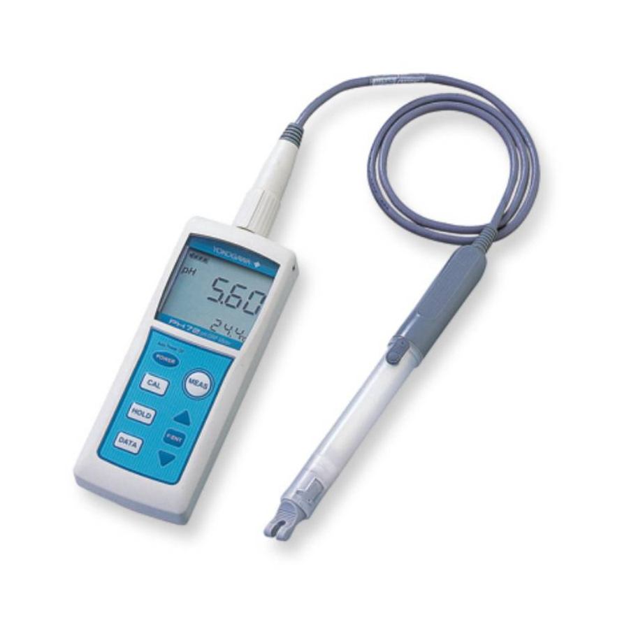
Can attach hand strap here Display Displays conductivity, temperature, and temperature coefficient simultaneously. Battery box cover fixing screw Key switches PERSONAL Instrument name plate SC METER with model number MODEL SC72 and serial number STYLE S1.0 E000001 2004. IM 12D03D02-01E... -
Page 14: Sensor Part Names And Functions
1. Outline Sensor Part Names and Functions Four types of sensors are available for use with the Model SC72 Personal Conductivity Meter: (1) sensor for high purity water measurement (cell constant 0.05 cm (2) general-purpose sensor (cell constant 5 cm... - Page 15 1. Outline Sensor for high purity water measurement General-purpose sensor SC72 - 21 - - AA - AA *1 SC72 - 11 - SC72 - 23 - - AA Model number and Model number and cell constants display plate cell constants display plate...
-
Page 16: Options (Available Separately)
(250mL) F010701.ai Spare Parts O-rings and gaskets are important parts to ensure that the SC72 meter is water resistant. Replace these parts as required. Refer to Section 5.5, “Storage and O-ring/ Gasket Replacement” for replacement. O-ring and gasket set (Part no.: K9654AY) - Page 17 1. Outline 1-10 IM 12D03D02-01E...
-
Page 18: Preparation
2. Preparation 2. Preparation Installing the Batteries Install the batteries first. In South Korea and Malaysia, primary battery is limited by regulations. Please use batteries with the authorized certification mark for each country. CAUTION Select a relatively moisture-free location when installing batteries in the meter. When installing batteries, observe correct polarity (battery orientation). -
Page 19: Connecting The Sensor Cable
2. Preparation Connecting the Sensor Cable Connect the sensor cable. CAUTION Select a relatively moisture-free location when connecting the sensor cable. When connecting the sensor cable, tighten by turning only the silver locknut, do not turn the cable or waterproof cover. Also take care not wet or contaminate the connector. -
Page 20: Setting Temperature Unit
2. Preparation Setting Procedure POWER After installing the batteries, press and hold key for at least one second. All LCD segments appears momentarily and then the date setting display starts automatically. Set year, month, day, hours, and minutes following the flowchart below. Note: If you attempt to abort the setting procedure before completing, the meter will beep three times and reject the attempt. -
Page 21: Setting Cell Constant
2. Preparation Setting Cell Constant Even for sensors of the same type, each sensor has its own distinct cell constant. So, set the proper cell constant as indicated on the sensor cable. Whenever sensors are replaced, be sure to change the cell constant setting in the meter accordingly. -
Page 22: Setting Temperature Compensation Coefficient
2. Preparation Setting Temperature Compensation Coefficient As described in Section 7.3, liquid conductivity varies with liquid temperature. Therefore, if concentration is measured by conductivity, the conductivity must be converted to equivalent conductivity at a certain temperature. This instrument incorporates standard temperature conversion functions to convert liquid conductivity measurements to equivalent conductivity at 25°C. - Page 23 2. Preparation Set the temperature compensation coefficient F/ENT for Function mode select t.Co for t.Co panel F/ENT For NaCl solutions Manual setting select NaCl or %/°C (%/°F) F/ENT Set the temperature F/ENT compensation coefficient with the keys. F/ENT MEAS MEAS The temperature coefficient you set is displayed here IM 12D03D02-01E...
-
Page 24: Measurement
(2) Check that the plastic cover (for general-purpose sensor) and outer electrode (for high purity water measurement) are secure. (3) Do not use the SC72 meter to measure liquids with temperatures over 80°C. (If the sensor grip is immersed, liquid temperature shall be below 50°C.) Do not use the meter to measure extremely corrosive liquids such as solutions of hydrofluoric acid. -
Page 25: Measurement Procedures
3. Measurement Measurement Procedures Dipping sensor into liquid To help avoid errors due to air bubbles around the sensor element (inner electrode), immerse the sensor into the liquid to be measured so that its air vent is below liquid level. To dislodge any air bubbles from the inner electrode, dip the sensor into the liquid and move it up and down two or three times. -
Page 26: Saving A Measured Value
3. Measurement Saving a Measured Value There are two ways to save a measured value: holding temporarily and storing as a record in nonvolatile memory. Measured values stored in nonvolatile memory are not deleted even by replacing the batteries. (1) HOLD key is pressed during measurement, the currently measured value is held HOLD temporarily and the displayed value no longer changes. - Page 27 3. Measurement IM 12D03D02-01E...
-
Page 28: Keypad And Display Functions
4. Keypad and Display Functions 4. Keypad and Display Functions There are seven membrane keys on the keyboard of the Personal Conductivity meter. The following key functions are provided. • Display the conductivity, measured temperature and temperature coefficient. • Display the conductivity, date and time. •... - Page 29 4. Keypad and Display Functions : DATA key DATA When pressed during measurement, mark flash and the currently displayed measured conductivity value and temperature are held temporarily. Pressing F/ENT key while mark is flashing, will store the held data in memory. After the data is stored successfully, the meter returns to measurement mode automatically.
-
Page 30: Display Items
4. Keypad and Display Functions Display Items Display items and their descriptions are provided below. Remaining battery life display Temp. compensation setting mode Manual range setting mode Data save mode HOLD mode Calibration with std. solution Cell constant set mode (1) Remaining battery life display Indicates the level of the remaining battery life stepwise. -
Page 31: Function Mode
4. Keypad and Display Functions Function Mode Outline Various functions are supported by function mode. Press key while the meter F/ENT is in measurement mode to move to function mode. Note: The last selected and executed item is displayed when you move to function mode. Use keys to cycle through the items listed in Table 4.1 in that order. - Page 32 4. Keypad and Display Functions Pressing keys scrolls through all stored data. If no data are stored, “no dAtA” is displayed at the bottom of the display. Each press of DATA key cycles through the day/month, year, and time of the stored data, and “Delete stored data” panels. •...
- Page 33 4. Keypad and Display Functions F/ENT to display other data Dsy, month data was stored Year that data was stored Stored measurement data DATA DATA Latest data DATA "Delete stored data" panel Time stored DATA F/ENT DATA F/ENT Delete stored data F/ENT When no stored data.
- Page 34 4. Keypad and Display Functions • Manual temperature compensation coefficient setting Press the keys to select %/°C (or %/°F). Then press the key. Use the F/ENT keys to set the temperature coefficient. Then press the key. F/ENT F/ENT keys to select For NaCl: When NaCl is displayed, F/ENT press...
- Page 35 Typical cell constants are as follows: For pure water sensor (SC72-11): 0.05 cm For general-purpose (SC72-21, -23) and chemical-resistant sensors (SC72-31): 5 cm Sensors for high-conductivity measurement: 50 cm When setting the cell constant, you should check the nameplate (attached to sensor cable) for the model number and cell constant.
- Page 36 Once the cell constant is set, it remains stored in memory even when batteries are removed. The general-purpose cell has the same cell constant whether used with SC72-21 or SC72-23 type. Refer to Sec. 2.4 for cell constant setting procedure.
- Page 37 4. Keypad and Display Functions (6) Delete all stored data (dEL.A) panel Used to delete all stored data. Press key on the flashing “dEL.A” panel. F/ENT will be flashing. Use keys to select . Press key to delete all F/ENT stored data completely.
- Page 38 4. Keypad and Display Functions Hour setting (24-hr clock) Minute setting F/ENT F/ENT F/ENT (9) Alarm time setting (ALM) panel Used to enable/disable the alarm clock and set the alarm clock in minutes and seconds. Use keys to select the desired alarm cycle: 7 days (everyday), 5 days (weekdays) or once.
- Page 39 4. Keypad and Display Functions F/ENT Hour setting (24-hr clock) alarm sounds F/ENT at preset time every day F/ENT Minute setting alarm sounds at preset time from Monday to Friday alarm sonds once at preset time (10) Set Auto Power Off time (A.oFF) panel Used to set the automatic power off time.
- Page 40 4. Keypad and Display Functions (11) Set beep on/off (bZ.o) panel The beep sound on key press can be enabled/disabled in this panel. Use keys F/ENT to select on or off and press key to confirm. Note that this beep setting does not affect the alarm sounding (see Item (9)).
- Page 41 4. Keypad and Display Functions (14) Check version number (VEr) panel Used to check the version number of the program. This is not user configurable. F/ENT (15) Defrag memory (dFLG) panel Up to 300 data can be stored. Unnecessary data can be individually deleted (refer to Item (1), “Display stored data”), but this individual deletion does not free up memory occupied by deleted data.
-
Page 42: Maintenance
5. Maintenance 5. Maintenance For Optimum Meter Performance The SC72 meter appears to be very simple, but is a precision instrument. To ensure that measurement accuracy is maintained, observe the following precautions regarding preliminary setting, measurement, maintenance and storage. Preliminary setting, measurement, maintenance and storage:... -
Page 43: Washing The Electrode
5. Maintenance Washing the Electrode Dirt or stains on the electrode may have an adverse effect on the cell constant, thereby making accurate conductivity measurement impossible. Therefore, after measurement, rinse the electrode in clean water (for example, tap water) to remove stains. -
Page 44: Cleaning And Drying Connectors
5. Maintenance Cleaning and Drying Connectors Deteriorated insulation between connector pins can cause inaccurate readings. To remove stains and/or moisture that may cause deteriorated insulation, clean the connector with a dry cloth or a cloth moistened with anhydrous alcohol. If necessary, use a dryer. -
Page 45: Calibration With Standard Solution
Note: Calibration with standard solution means to measure a standard solution of accurately- known conductivity and to adjust SC72 meter so that the displayed measured value is the same as the known conductivity value of the standard solution. If the sensor has been used for a long time, and does not look clean despite washing, recalibrate the SC72 meter with standard solution to check if cell constant is normal. - Page 46 5. Maintenance Before calibrating the meter with standard solution, check that the electrode is clean. If stains are found, clean the electrode first. Also check that the cover (of general-purpose sensor) and outer electrode (of sensor for high purity water measurement) are secure. Cell constant is affected by stains or loose cover.
- Page 47 5. Maintenance Procedures for calibration with standard solution POWER Water F/ENT Std. sol. Thoroughly wipe off the Select Wash sensor with washing water from the CAL mode water completely. electrodes before immersing the sensor in standard solution. F/ENT Least significant figit of the Whole measurement value measuremet value is flashing is flashing...
-
Page 48: Storage And O-Ring/Gasket Replacement
O-ring from staining. Contamination may cause deteriorated insulation of connectors or poor water resistance by the O-ring. (3) Do not place any object on top of the sensor or on the top of the SC72 meter. Storage Location When not in use, store the meter and sensor in a safe place. If it is to be stored for a long period, store it in a place: •... - Page 49 (2) Replacing the Gasket Install the gasket on the groove on the battery box so the raised part fits in place as shown below. The gasket is symmetrical right to left and front to back. Gasket SC72 meter top Raised part IM 12D03D02-01E...
-
Page 50: Troubleshooting
(3) Is SC72 meter unserviceable? If any problem is evident, follow the procedure shown in Section 6.2 to determine the cause and fix the problem. If you cannot fix it, contact your nearest Yokogawa sales office. • Displayed value unstable Abnormal •... - Page 51 • Use correct standard solution conductivity. (Refer to Sec. 5.4) • Replace the sensor. (Refer to Sec. 1.6) (4) Err6 Meter electronics failure Possible Causes: Err6 occurs if the meter electronics fails. Corrective Actions: • Contact your nearest Yokogawa sales office. IM 12D03D02-01E...
-
Page 52: Causes Of Abnormal Measured Value
6. Troubleshooting (5) or Out of measurement range Possible Cause: Conductivity is over the maximum value on the range. Corrective Action: For manual ranging, select an appropriate range. If value exceeds maximum of highest range (or when on autorange), use a more appropriate sensor (see Sec. 4.3 (3)). - Page 53 6. Troubleshooting IM 12D03D02-01E...
-
Page 54: Measuring Principles Of This Instrument
7. Measuring Principles of this Instrument 7. Measuring Principles of this Instrument What Is Conductivity? Conductivity of a solution is defined as the ability of the solution to conduct electric current. It is the reciprocal of the resistance between two sensors (both of areas 1 m at a distance of 1 m apart in the solution. -
Page 55: Principles Of Operation
7. Measuring Principles of this Instrument Principles of Operation AC power supply Ammeter Figure 7.2 Operational Schematic Dip two metallic plates (used as sensor electrodes) in a solution and apply a certain voltage to flow current (I): where Rc = solution resistance between two sensors The relationship between Rc and conductivity K is expressed by: Rc = J •... - Page 56 100 124.5 x (31.0 – 25) – 147.6 x (18.0 – 25) 23.1 x 100 747.0 – (–1033.2) = 1.298 Set the temperature coefficient 1.30 in the SC72 meter (as meter allows three digits to be entered). IM 12D03D02-01E...
-
Page 57: Wetted Part Materials Of Sensors
7. Measuring Principles of this Instrument • Checking if meter is working correctly When the temperature coefficient already set is accurate, the conductivity displayed should be constant regardless of liquid temperature (within permitted temperature range). Check that the temperature coefficient already set is accurate. When the liquid temperature is lowered, if a larger conductivity is indicated, the temperature coefficient already set is too small;... -
Page 58: Appendix
Appendix Appendix Key-Operation Flow Chart (for reference) Typical screens are shown. Refer to the corresponding section in the body of the manual for details. ● When turn on power Toggle display type POWER First time used, or MEAS after replace batteries F/ENT MEAS F/ENT... - Page 59 Appendix ● Function Mode Temperature compensation setting Display stored measurement value Range selection F/ENT F/ENT F/ENT F/ENT DATA F/ENT F/ENT DATA F/ENT F/ENT DATA DATA F/ENT F/ENT F02.ai App-2 IM 12D03D02-01E...
- Page 60 Appendix ● Function Mode Calibration with Delete all stored Cell constant setting Date setting Time setting standard solution measurement data F/ENT F/ENT F/ENT F/ENT F/ENT F/ENT F/ENT F/ENT F/ENT F/ENT F/ENT F/ENT F/ENT F/ENT ● Switching to Function Mode ● Reverting to Measurement Mode Measurement status Measurement status MEAS...
- Page 61 Appendix ● Function Mode Set Auto Power OFF Alarm time setting Set buzzer ON/OFF Set measurement unit Set temperature unit interval F/ENT F/ENT F/ENT F/ENT F/ENT F/ENT F/ENT F/ENT F/ENT F/ENT F/ENT ● Function Mode Version number Deflagment display storaged data F/ENT F/ENT F/ENT...
-
Page 62: Revision Record
Revision Record Manual Title : Model SC72 Personal Conductivity Meter Manual Number : IM 12D03D02-01E Edition Date Remark (s) June 2021 Change of accessories, deletion of optional accessories, revi- sion of specifications (RoHS conformity standards), etc., full review Aug. 2009 Change of information on EMC compliance: P.1-3 Apr.
Need help?
Do you have a question about the SC72 and is the answer not in the manual?
Questions and answers