
Related Manuals for YOKOGAWA VagilantPlant SR10006


Summary of Contents for YOKOGAWA VagilantPlant SR10006
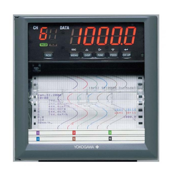
- Page 1 User’s Models SR10001/SR10002/SR10003/SR10004/ Manual SR10006 SR10000 Recorder IM 04P03B01-01E 2nd Edition Yokogawa Electric Corporation...
-
Page 2: Foreword
Networking Software, Release 1 that has been licensed from the University of California. Trademarks • All the brands or names of Yokogawa Electric’s products used in this manual are either trademarks or registered trademarks of Yokogawa Electric Corporation. • Microsoft, MS-DOS, Windows, Windows NT, and Windows XP are either registered trademarks or trademarks of Microsoft Corporation in the United States and/or other countries. -
Page 3: How To Use This Manual
How to Use This Manual Structure of the Manual Read the Operation Guide first to familiarize yourself with the basic operation, and then read this manual. For a description of the communication function, see the SR10000 Communication Interface User's Manual (IM 04P03B01-17E) . This user's manual consists of the following sections. - Page 4 How to Use This Manual Conventions Used in This Manual Unit K ..Denotes 1024. Example: 768 KB (file size) k ..Denotes 1000. Safety Markings The following markings are used in this manual. Improper handling or use can lead to injury to the user or damage to the instrument.
-
Page 5: Table Of Contents
Contents Foreword ............................i How to Use This Manual ......................... ii Chapter 1 Functional Explanation and Setup Guide Measuring Input Section ....................1-1 Alarms ..........................1-6 Recording ......................... 1-8 Remote Control Function (/R1 Option) ................1-19 Other Functions ......................1-21 Function Setup Guide .................... - Page 6 Contents 4.12 Enabling the Partial Expanded Recording Function ............4-17 4.13 Changing the Printout Font .................... 4-18 4.14 Changing the Print/Display Format of the Date ............. 4-19 4.15 Enabling the Bias, Low-Cut, and Calibration Correction (/CC1 Option) Functions ..4-20 4.16 Changing the Time Printout Format ................
-
Page 7: Chapter 1 Functional Explanation And Setup Guide
Chapter 1 Functional Explanation and Setup Guide Measuring Input Section Input Section Number of Measurement Channels and Scan Interval The recorder samples the input signals on the measurement channels at the scan interval to obtain the measured values. Model Number of Channels Scan Interval 1-pen model 125 ms... - Page 8 1.1 Measuring Input Section • Delta Computation The value obtained by subtracting the measured value of another channel (called the reference channel ) from the input value of the channel set to delta computation is used as the measured value of that channel. The reference channel must be assigned to a channel whose channel number is less than that of the channel on which delta computation is specified.
- Page 9 1.1 Measuring Input Section • Bias A given value (bias value) is added to the input value and used as the measured value of that channel. Biased channel Input value Measured value Bias value <Related Topics> Setting the bias: Sections 4.15 and 3.10 •...
- Page 10 1.1 Measuring Input Section Note When using external reference junction compensation, set an appropriate reference junction compensation voltage. For example, if the reference junction temperature of the external reference compensation is T °C, set the reference compensation junction voltage to the thermoelectromotive force of the 0°C reference of T °C.
- Page 11 1.1 Measuring Input Section Integration Time of the A/D Converter The recorder uses an A/D converter to convert the sampled analog signal to a digital signal. By setting the integration time of the A/D converter to match the time period corresponding to one cycle of the power supply or an integer multiple of one cycle, the power supply frequency noise can be effectively suppressed.
-
Page 12: Alarms
Alarms This function generates an alarm when the measured data meets a certain condition. The alarm status is displayed on the screen while recording the alarm occurrence/ release on the chart paper. Also, alarm output relays can be used to output contact signals when alarms occur (/A1, /A2, and /A3 options). - Page 13 1.2 Alarms Alarm Indication When an alarm occurs, the ALM indicator in the status display section illuminates, and the 2 digit of the LED shows the alarm status for each channel. When the alarm clears, the indicator and the LED turn OFF. Alarm Recording The alarm occurrence/release can be recorded on the chart paper.
-
Page 14: Recording
Recording The recorder is capable of recording the measured values with pens or dots (trend recording) as well as various other types of information. Trend Recording The measured values are printed within a width of 100 mm. Recording Method (Pen Model) •... - Page 15 1.3 Recording Partial Expanded Recording This function expands a section of the recording range. By default, partial expanded recording is disabled. Compressed Expanded <Related Topics> Setting the partial expanded recording: Sections 4.12 and 3.5 Pen Offset Compensation (Pen Model) This function compensates for the pen offset (phase difference) along the time axis. On 2-pen, 3-pen, and 4-pen recorders, there are offsets along the time axis (phase difference) between the pens.
- Page 16 1.3 Recording Printout The figure below is used to explain the printout contents. The actual printout and font are different from those illustrated in the figure. The printout positions are also slightly different. Printout Example on the Pen Model Manual printout Jan.31.05 15:00 223.5mg/cm 437.2µS/cm...
- Page 17 1.3 Recording Printout Example on the Dot Model Manual printout Jan.31.05 16:00 223.5mg/cm 437.2µS/cm −0.222V 591.6˚C −0.665V 6 L −0.448V New chart speed printout _50mm/h 14:55 Periodic printout Jan.31.05 13:50 Time tick 218.7mg/cm 390.6µS/cm 598.4˚C −0.222V Scale −0.995V L −0.448V 500.0 mg/cm Delta computation...
- Page 18 1.3 Recording Periodic Printout Values such as the measured values are printed at a determined interval. The contents of the printout vary between the pen model and dot model. Printout cannot be performed at the following chart speeds. Pen model: 1800 mm/h or higher; Dot model: 120 mm/h or higher Channel No.
- Page 19 1.3 Recording Alarm Printout Alarm information is printed when an alarm occurs or releases. Printout cannot be performed at the following chart speeds. Pen model: 1800 mm/h or higher; Dot model: 120 mm/h or higher Time of alarm occurrence/release Indicates that there are alarms that are not printed because the alarm printout buffer is full.
- Page 20 1.3 Recording Recording Start Printout Printout cannot be performed at the following chart speeds. Pen model: 1800 mm/h or higher; Dot model: 120 mm/h or higher When recording is started, the time tick (dot model), the time, and the chart speed can be printed.
- Page 21 1.3 Recording Setting Printout List or setup list can be printed. When setting printout is executed, trend recording stops and restarts when the printout is complete. List printout contains Setting Mode settings such as the input range and alarm for each channel.
- Page 22 1.3 Recording • Printout Example of List on the Dot Model The printout examples may appear differently from the actual printout as a result of functional improvements made on the recorder after this manual was written. For the procedure to set the functions, see section 1.6, “Function Setup Guide.” 1-16 IM 04P03B01-01E...
- Page 23 1.3 Recording Header Printout (/BT1 Option) When recording is started, the Start printout is performed, and recording starts. During trend recording, you can print out messages (up to 5) that include measured values. When recording is stopped, End printout is performed. Operation 1.
- Page 24 1.3 Recording • Switching between Start Printout and Start printout 2, and between End printout and End printout 2 With the remote control function (/R1 option), you can change the items that are printed out. For example, when a process ends successfully, End printout is performed and the lot number is updated.
-
Page 25: Remote Control Function (/R1 Option)
Remote Control Function (/R1 Option) Specified operations can be carried out by applying remote signals (contact or open collector signals) to the remote control input terminals. There are five remote control input terminals. An action can be assigned to each terminal. - Page 26 1.4 Remote Control Function (/R1 Option) • Switching Batch Comment (/BT1 Option) • Remote input signal: Level • Switches between Start printout and Start printout 2, and between End printout and End printout 2 depending on the status of the batch comment switching signal when recording is started/stopped remotely.
-
Page 27: Other Functions
Other Functions Key Lock Key lock is a function that prohibits key operations. When key lock is enabled, pressing keys produces no effect. To release the key lock, a password is entered. Key Lock Items Each of the following keys can be included or excluded from the key lock function. Keys that can be locked In the case of the FUNC key, each function of the FUNC key can be included or excluded from the key lock function. - Page 28 1.5 Other Functions If the recorder is used in a region that has DST, time can be switched automatically between DST and standard time by setting the date/time when switching from the standard time to DST and the date/time when switching back from DST to standard time. When switching from standard time to DST, the clock is set ahead by 1 hour.
-
Page 29: Function Setup Guide
Function Setup Guide This section explains the settings necessary to use various functions of the recorder. Read the section corresponding to the function you wish to use. Note This section contains all the settings related to each item. If the desired setting is the same as the default value, you do not have to set it. - Page 30 1.6 Function Setup Guide Item Description Reference Section RJC of TC input Use RJC in Basic Setting mode to select whether to use the internal RJC function or an external RJC function. Filter (pen model) Use FILTR in Basic Setting mode and select Use or Not. 4.11 If Use is selected, set the filter time constant using AUX >...
- Page 31 1.6 Function Setup Guide Item Description Reference Section Periodic printout Mar.31.2006! Channel number 15:50* or tag 1.000V Measured value -1.000V 0.000 2.000 Scale Recording color 50mm/h_ (pen model) • Enable/Disable the periodic printout Use PER. in Basic Setting mode to turn ON/OFF the periodic printout. •...
- Page 32 1.6 Function Setup Guide Item Description Reference Section Switching between Start printout and Start printout 2, and between End printout and End printout 2 (/BT1, /R1 option) • Switching settings Assign DUAL (Batch comment switching) to the remote control input terminal. 4.18 Use BATCH >...
-
Page 33: Chapter 2 Frequently Used Setup Operations (Setting Mode)
Chapter 2 Frequently Used Setup Operations (Setting Mode) Setting the Input Range Input range can be set for each measurement channel. Set unused channels to Skip. If you change the input range, set the bias, alarm, partial expanded recording, and calibration correction again. - Page 34 2.1 Setting the Input Range Description • Selectable Range of Input Range, Span Left, and Span Right The input range, span left, and span right can be set in the range shown below. Span left and span right cannot be set to the same value. DC voltage ( Range Type Selectable Span Range...
- Page 35 2.1 Setting the Input Range 1-5V Input Select “RANGE.” (RANGE) Select the channel number. (CH1) Select “1-5V.” (1-5V) Channel number Set the left span value. Span left Set the right span value. Span right Select the left scale value and the decimal place. Scale left Decimal point Select the right scale value.
- Page 36 2.1 Setting the Input Range Linear Scaling Select “RANGE.” (RANGE) Select the channel number. (CH1) Select “SCALE.” (SCALE) Channel number Select the input type. (VOLT) Select the range. (2V) Set the left span value. Span left Set the right span value. Span right Select the left scale value and the decimal place.
- Page 37 2.1 Setting the Input Range Delta Computation Select “RANGE.” (RANGE) Select the channel number. (CH2) Select “DELTA.” (DELTA) Channel number Select the reference channel. (CH1) Set the left span value. Span left Set the right span value. Span right The settings are activated. (OK) Description •...
- Page 38 2.1 Setting the Input Range ON/OFF Input Select “RANGE.” (RANGE) Select the channel number. (CH1) Select “DI.” (DI) Channel number Select contact or level. (CONT) Set the left span value. Span left Set the right span value. Span right The settings are activated. (OK) Description •...
- Page 39 2.1 Setting the Input Range Square Root Computation Select “RANGE.” (RANGE) Select the channel number. (CH1) Select “SQRT.” (SQRT) Channel number Select from the range types of DC voltage. 20 mV, 60 mV, 200 mV, 2 V, 6 V, 20 V, or 50 V (2V) Set the left span value.
- Page 40 2.1 Setting the Input Range • Low-Cut and Low-Cut Point If low-cut is set to ON, set the low-cut point. Selectable range of the low-cut point: 0.0 to 5.0% of the recording span Values below the low-cut point is set to 0% of the recording span (scale left value). <Related Topics>...
-
Page 41: Setting The Alarm
Setting the Alarm An alarm can be set for each channel. If you change the input range, set the alarm again. Procedure Hold down the key for 3 seconds to enter Setting mode. MENU Carry out the procedure shown in the figure below. Press the key to select the value. - Page 42 2.2 Setting the Alarm Explanation Alarm Type Symbol Name Notes High limit alarm Low limit alarm Difference high limit alarm Can be specified on channels set to delta computation. Difference low limit alarm Can be specified on channels set to delta computation. Note On channels set to delta computation, alarms can be detected on the values illustrated in the figure below.
-
Page 43: Setting The Unit On Linearly Scaled Channels
Setting the Unit on Linearly Scaled Channels Units can be assigned on channels whose input range is set to Scale, 1-5V, or SQRT.The assigned unit is added when printing to the chart paper or during data transmission. Procedure Hold down the key for 3 seconds to enter Setting mode. -
Page 44: Changing The Chart Speed
Changing the Chart Speed The chart speed can be changed. Procedure Hold down the key for 3 seconds to enter Setting mode. MENU Carry out the procedure shown in the figure below. Press the key to select the value. If you press the key, the operation is cancelled, and the display returns to a higher level menu. -
Page 45: Setting The Date/Time
Setting the Date/Time The date/time can be set. Procedure Hold down the key for 3 seconds to enter Setting mode. MENU Carry out the procedure shown in the figure below. Press the key to select the value. For the procedure on how to enter values or characters, see page 19 in the Operation Guide . -
Page 46: Chapter 3 Setup Operations For Convenient Functions (Setting Mode)
Chapter 3 Setup Operations for Convenient Functions (Setting Mode) Setting the Trend Recording Interval (Dot Model) The trend recording interval (dot printing interval) on the dot model can be set. Procedure Hold down the key for 3 seconds to enter Setting mode. MENU Carry out the procedure shown in the figure below. -
Page 47: Setting The Filter (Pen Model)
Setting the Filter (Pen Model) A filter can be set on the measurement channels on the pen model. Procedure Hold down the key for 3 seconds to enter Setting mode. MENU Carry out the procedure shown in the figure below. Press the key to select the value. -
Page 48: Setting The Moving Average (Dot Model)
Setting the Moving Average (Dot Model) The moving average function can be set on the measurement channels on the dot model. Procedure Hold down the key for 3 seconds to enter Setting mode. MENU Carry out the procedure shown in the figure below. Press the key to select the value. -
Page 49: Setting Recording Zones For Each Channel (Zone Recording)
Setting Recording Zones for Each Channel (Zone Recording) A recording zone can be set for each measurement channel. Procedure Hold down the key for 3 seconds to enter Setting mode. MENU Carry out the procedure shown in the figure below. Press the key to select the value. -
Page 50: Setting The Partial Expanded Recording
Setting the Partial Expanded Recording A section of the recording range can be expanded. If you change the input range, set the partial expanded recording again. Procedure Hold down the key for 3 seconds to enter Setting mode. MENU Carry out the procedure shown in the figure below. Press the key to select the value. -
Page 51: Turning Trend Recording (Dot Model) And Periodic Printout On/Off For Each Channel
Turning Trend Recording (Dot Model) and Periodic Printout ON/OFF for Each Channel This section explains the details of setting the trend recording and periodic printout for each measurement channel. Procedure Hold down the key for 3 seconds to enter Setting mode. MENU Carry out the procedure shown in the figure below. -
Page 52: Setting Tags On Channels
Setting Tags on Channels Tags can be assigned to measurement channels. Procedure Hold down the key for 3 seconds to enter Setting mode. MENU Carry out the procedure shown in the figure below. Press the key to select the value. For the procedure on how to enter values or characters, see page 19 in the Operation Guide . -
Page 53: Setting The Message String
Setting the Message String Message strings to be printed on the chart paper can be set. Up to five message strings can be registered. Procedure Hold down the key for 3 seconds to enter Setting mode. MENU Carry out the procedure shown in the figure below. Press the key to select the value. -
Page 54: Setting The Secondary Chart Speed (Remote Control Function, /R1)
Setting the Secondary Chart Speed (Remote Control Function, /R1) The secondary chart speed when the chart speed is to be switched using the remote control function (/R1 option) can be set. Procedure Hold down the key for 3 seconds to enter Setting mode. MENU Carry out the procedure shown in the figure below. -
Page 55: Applying A Bias On The Measuring Input Signal
3.10 Applying a Bias on the Measuring Input Signal A bias can be applied to the scaled value of the measuring input signal. If you change the input range, set the bias again. Procedure Hold down the key for 3 seconds to enter Setting mode. MENU Carry out the procedure shown in the figure below. -
Page 56: Performing Calibration Correction (/Cc1 Option)
3.11 Performing Calibration Correction (/CC1 Option) The scaled values of the measuring input signal are corrected using specified segments, and the results are used as measured values. If you change the input range, set the measured and correction values again. Procedure Hold down the key for 3 seconds to enter Setting mode. - Page 57 3.11 Performing Calibration Correction (/CC1 Option) Press the key to set other channels. If you are done, press the key. Hold down the key for 3 seconds to return to Operation mode. MENU Explanation Setting Measured and Corrected Values • Using revise values Measured value Correction using revise values...
-
Page 58: Setting Up Start Printout And End Printout (/Bt1 Option)
3.12 Setting Up Start Printout and End printout (/BT1 Option) Enter settings for Start printout/Start printout 2 when starting recording, and for End printout/End printout 2 when stopping recording. Before entering settings, enable “Start printout and End printout” in Basic Setting mode. Procedure Hold down the key for 3 seconds to enter Setting mode. - Page 59 3.12 Setting Up Start Printout and End printout (/BT1 Option) Setting the Lot Number Select “BATCH.” (BATCH) (When LOT is 4 or 6 digits) Select “LOT” (lot number). (LOT) Enter the 1 digit. digit Enter the 2 digit. digit Enter the 6 digit.
- Page 60 3.12 Setting Up Start Printout and End printout (/BT1 Option) Selecting Printout ON/OFF for the Batch Name, Chart Speed, and Date/Time. Select “BATCH.” (BATCH) Select “DETAI” (Batch details). (DETAI) (Start 2 and End 2 can be selected when dual comment is set to USE) Select a mode.
- Page 61 3.12 Setting Up Start Printout and End printout (/BT1 Option) Setting the Feed Amount, Lot Number Update, and Ejection of Pen Offset Compensating Data Select “BATCH.” (BATCH) Select “DETAI” (Batch details). (DETAI) (Start 2 and End 2 can be selected when dual comment is set to USE) Select a mode.
- Page 62 3.12 Setting Up Start Printout and End printout (/BT1 Option) Explanation Batch Number You can enter up to 26 characters. Lot Number Enter using a 4 or 6 digit number. Select which number of digits to use (4 or 6) under “Lot No.”...
-
Page 63: Regarding The Message Format (/Bt1 Option)
3.13 Regarding the Message Format (/BT1 Option) In the 5 message printouts, up to 35 characters can be printed out including the date/ time and measured values. Messages including measured values can be printed out even when start printout or stop printout is disabled. Procedure The message format cannot be set by key operation. - Page 64 3.13 Regarding the Message Format (/BT1 Option) • Character String Format The format for message strings is L01 (1 character), L02 (2 characters), ..L16 (16 characters). In the example on the previous page, L09 indicates “Process-1” and L02 indicates “°C .” <Related Topics>...
-
Page 65: Setting The Date/Time For Switching Between Standard Time And Dst
3.14 Setting the Date/Time for Switching between Standard Time and DST The date/time for switching from the standard time to DST and the date/time for switching back from DST to standard time can be set, if the recorder is used in a region that has DST. - Page 66 3.14 Setting the Date/Time for Switching between Standard Time and DST If you are done, press the key. Hold down the key for 3 seconds to return to Operation mode. MENU Explanation Start Month, Start Day, and Start Time Set the date/time for switching from standard time to DST. Specify the day as the n of the week of the month.
-
Page 67: Chapter 4 Setup Operations For Changing/Adding Functions (Basic Setting Mode)
Chapter 4 Setup Operations for Changing/Adding Functions (Basic Setting Mode) Changing the Auxiliary Alarm Function This section explains the details of setting the alarm system items listed below. • Diagnosis output using the alarm output relay (I01) • Energized/De-energized operation of alarm output relays when alarms occur •... - Page 68 4.1 Changing the Auxiliary Alarm Function Explanation Diagnosis Output When set to ON, alarm output relay I01 becomes a dedicated diagnosis output relay, and the operation is fixed to de-energized. Diagnosis output is a function which outputs a relay signal when an error is detected in the recording section, burnout detection function, or the A/D converter.
-
Page 69: Changing The Integration Time Of The A/D Converter
Changing the Integration Time of the A/D Converter The integration time of the A/D converter can be set. Basic Setting mode cannot be entered when recording is in progress. Procedure Hold down the key for 3 seconds to enter Setting mode. MENU Hold down the keys simultaneously for 3 seconds to display the... -
Page 70: Setting The Burnout Detection Function
Setting the Burnout Detection Function The burnout detection function of thermocouples can be set on 1-5V or TC input channels. Basic Setting mode cannot be entered when recording is in progress. Procedure Hold down the key for 3 seconds to enter Setting mode. MENU Hold down the keys simultaneously for 3 seconds to display the... -
Page 71: Setting The Rjc Function On Tc Input Channels
Setting the RJC Function on TC Input Channels The RJC mode can be set on TC input channels. Basic Setting mode cannot be entered when recording is in progress. Procedure Hold down the key for 3 seconds to enter Setting mode. MENU Hold down the keys simultaneously for 3 seconds to display the... -
Page 72: Changing The Channel Recording Color (Dot Model)
Changing the Channel Recording Color (Dot Model) The trend recording color on the dot model can be changed. Basic Setting mode cannot be entered when recording is in progress. Procedure Hold down the key for 3 seconds to enter Setting mode. MENU Hold down the keys simultaneously for 3 seconds to display the... -
Page 73: Recording By Compensating For The Pen Offset Along The Time Axis (Pen Model)
Recording by Compensating for the Pen Offset along the Time Axis (Pen Model) The pen offset along the time axis (pen model) can be compensated. Basic Setting mode cannot be entered when recording is in progress. Procedure Hold down the key for 3 seconds to enter Setting mode. -
Page 74: Turning Printouts On/Off
Turning Printouts ON/OFF (Selecting the Channel/Tag Printout and Turning ON/OFF the Channel, Alarm, Recording Start, New Chart Speed, Scale, and Pen Color Printouts) Select whether to print using channel numbers or tags and set whether to print the various printout items. Basic Setting mode cannot be entered when recording is in progress. - Page 75 4.7 Turning Printouts ON/OFF From the previous page Scale printout (SCALE) Select whether to print the channel scale in periodic printout. Select ON or OFF. (ON) Recording color printout (pen model only) Select whether to print the recording color (PEN) in periodic printout.
-
Page 76: Turning Periodic Printout On And Off And Setting The Interval
Turning Periodic Printout ON and OFF and Setting the Interval The periodic printout settings can be specified. Basic Setting mode cannot be entered when recording is in progress. Procedure Hold down the key for 3 seconds to enter Setting mode. MENU Hold down the keys simultaneously for 3 seconds to display the... - Page 77 4.8 Turning Periodic Printout ON and OFF and Setting the Interval Interval Select the interval from 10, 12, 15, 20, 30 minutes, 1, 2, 3, 4, 6, 8, 12, and 24 hours ). However, printout might not take place at the specified interval depending on the chart speed and items printed (for details, see appendix 1).
-
Page 78: Setting The Key Lock
Setting the Key Lock The keys that can be locked and the password for releasing the key lock can be set. Basic Setting mode cannot be entered when recording is in progress. Procedure Hold down the key for 3 seconds to enter Setting mode. MENU Hold down the keys simultaneously for 3 seconds to display the... - Page 79 4.9 Setting the Key Lock From the previous page List printout (LIST) Select whether to lock the key (LOCK or FREE). (FREE) Setup list printout (SLIST) Select whether to lock the key (LOCK or FREE). (FREE) Message printout (MSG) Select whether to lock the key (LOCK or FREE).
- Page 80 4.9 Setting the Key Lock Explanation Key Lock Select the target keys ( Not use the key lock ( Password Sets the password for releasing the key lock. Set the password using a four-digit number. Operation of Keys to Be Key-Locked Sets the operation of the keys to be key-locked.
-
Page 81: Enabling The Moving Average Function (Dot Model)
4.10 Enabling the Moving Average Function (Dot Model) The moving average function can be enabled/disabled on the dot model. Basic Setting mode cannot be entered when recording is in progress. Procedure Hold down the key for 3 seconds to enter Setting mode. MENU Hold down the keys simultaneously for 3 seconds to display the... -
Page 82: Enabling The Filter Function (Pen Model)
4.11 Enabling the Filter Function (Pen Model) The input filter function on the pen model can be enabled/disabled. Basic Setting mode cannot be entered when recording is in progress. Procedure Hold down the key for 3 seconds to enter Setting mode. MENU Hold down the keys simultaneously for 3 seconds to display the... -
Page 83: Enabling The Partial Expanded Recording Function
4.12 Enabling the Partial Expanded Recording Function The partial expanded recording function can be enabled/disabled. Basic Setting mode cannot be entered when recording is in progress. Procedure Hold down the key for 3 seconds to enter Setting mode. MENU Hold down the keys simultaneously for 3 seconds to display the Basic Setting mode screen. -
Page 84: Changing The Printout Font
4.13 Changing the Printout Font The printout font can be changed. Changing the font changes the characters that can be used for message printouts, tags, and header printouts (/BT1 option). Basic Setting mode cannot be entered when recording is in progress. Procedure Hold down the key for 3 seconds to enter Setting mode. -
Page 85: Changing The Print/Display Format Of The Date
4.14 Changing the Print/Display Format of the Date The format of the printout and display of the year, month, and day can be changed. Basic Setting mode cannot be entered when recording is in progress. Procedure Hold down the key for 3 seconds to enter Setting mode. MENU Hold down the keys simultaneously for 3 seconds to display the... -
Page 86: Enabling The Bias, Low-Cut, And Calibration Correction (/Cc1 Option) Functions
4.15 Enabling the Bias, Low-Cut, and Calibration Correction (/CC1 Option) Functions The bias, low-cut, and calibration correction functions can be enabled/disabled. Basic Setting mode cannot be entered when recording is in progress. Procedure Hold down the key for 3 seconds to enter Setting mode. MENU Hold down the keys simultaneously for 3 seconds to display the... - Page 87 4.15 Enabling the Bias, Low-Cut, and Calibration Correction (/CC1 Option) Functions Explanation Bias Enable ( ): Enables the setting of the bias value in Setting mode. Disable ( ): The “BIAS” item does not appear in Setting mode. SQRT Low-Cut Sets the low-cut function for the square root computation.
-
Page 88: Changing The Time Printout Format
4.16 Changing the Time Printout Format The time printout format can be changed on the alarm printout, message printout, recording start printout, and new chart speed printout. Basic Setting mode cannot be entered when recording is in progress. Procedure Hold down the key for 3 seconds to enter Setting mode. - Page 89 4.16 Changing the Time Printout Format Explanation Selecting the Printout Format Select the time format of the alarm printout, message printout, recording start printout, and new chart speed printout. • Alarm Printout, Recording Start Printout, and New Chart Speed Printout H:M ( Hour:Minute H:M:S (...
-
Page 90: Initializing The Settings
4.17 Initializing the Settings This section explains the details of initializing the recorder settings to their factory default. Be careful, because all settings except the date/time and the adjustment values of the pen position and printer carriage position will be initialized. Basic Setting mode cannot be entered when recording is in progress. -
Page 91: Assigning Functions To The Remote Control Input Terminals (/R1 Option)
4.18 Assigning Functions to the Remote Control Input Terminals (/R1 Option) Functions can be assigned to the remote control input terminals. Basic Setting mode cannot be entered when recording is in progress. Procedure Hold down the key for 3 seconds to enter Setting mode. MENU Hold down the keys simultaneously for 3 seconds to display the... - Page 92 4.18 Assigning Functions to the Remote Control Input Terminals (/R1 Option) Explanation Remote Numbers The remote control input terminal numbers are from 1 to 5. Functions to Be Assigned RCD ( Starts/stops recording. C_SPD ( Changes the chart speed. T_ADJ ( Adjusts the internal clock to the nearest hour.
-
Page 93: Selecting To Show/Hide The Func Key Menus
4.19 Selecting to Show/Hide the FUNC Key Menus Select the menu for showing/hiding the FUNC key menus. Basic Setting mode cannot be entered when recording is in progress. Procedure Hold down the key for 3 seconds to enter Setting mode. MENU Hold down the keys simultaneously for 3 seconds to display the... - Page 94 4.19 Selecting to Show/Hide the FUNC Key Menus If you are done, press the key. To return to the Operation mode, 1. Press the key, use the key to select , and press the key. 2. Press the key to select , and press the key.
-
Page 95: Selecting To Show/Hide Setting Mode Menus
4.20 Selecting to Show/Hide Setting Mode Menus Select the menu for showing/hiding the Setting mode menus. Basic Setting mode cannot be entered when recording is in progress. Procedure Hold down the key for 3 seconds to enter Setting mode. MENU Hold down the keys simultaneously for 3 seconds to display the Basic Setting mode screen. - Page 96 4.20 Selecting to Show/Hide Setting Mode Menus From the previous page Select whether to display AUX in (AUX) Setting mode. Select ON or OFF. (ON) (Models with the /CC1 option) (CALIB) Select whether to display CALIB in Setting mode. Select ON or OFF. (ON) (Models with the /BT1 option) (B.NAME)
-
Page 97: Enabling/Disabling The Customized Menu
4.21 Enabling/Disabling the Customized Menu When the Customized menu is enabled, the following changes can be made. • Hide specified menu items from the FUNC key menu. • Hide specified Setting mode menu items. • Lock Basic Setting mode. Basic Setting mode cannot be entered when recording is in progress. Procedure Enabling the Customized Menu Hold down the... - Page 98 4.21 Enabling/Disabling the Customized Menu Disabling the Customized Menu Hold down the key for 3 seconds to enter Setting mode. MENU Hold down the keys simultaneously for 3 seconds to display the Basic Setting mode screen. Carry out the procedure shown in the figure below. Press the key to select the value.
- Page 99 4.21 Enabling/Disabling the Customized Menu Explanation Enable ( ): Locks Basic Setting mode and hides the specified menu items in Setting mode and FUNC key menu items. Disable ( ): Releases Basic Setting mode and shows the all menu items in Setting mode and all FUNC key menu items.
-
Page 100: Setting The Calibration Correction Function (/Cc1 Option)
4.22 Setting the Calibration Correction Function (/CC1 Option) The calibration correction method and the number of correction points can be set. Basic Setting mode cannot be entered when recording is in progress. Procedure Hold down the key for 3 seconds to enter Setting mode. MENU Hold down the keys simultaneously for 3 seconds to display the... -
Page 101: Enabling Start Printout, End Printout, And Message Format (/Bt1 Option)
4.23 Enabling Start Printout, End printout, and Message Format (/BT1 Option) This section explains the details of enabling/disabling the Start printout, End printout, and Message format. Basic Setting mode cannot be entered when recording is in progress . Procedure Hold down the key for 3 seconds to enter Setting mode. - Page 102 4.23 Enabling Start Printout, End printout, and Message Format (/BT1 Option) Explanation Start printout and End printout USE ( ): When starting/stopping recording, performs Start printout and End printout. You can now set “Start printout and End printout” under “Lot number,”...
-
Page 103: Changing The Temperature Unit
4.24 Changing the Temperature Unit The unit of the temperature measured using the TC or RTD can be changed. Basic Setting mode cannot be entered when recording is in progress. Procedure Hold down the key for 3 seconds to enter Setting mode. MENU Hold down the keys simultaneously for 3 seconds to display the... -
Page 104: Chapter 5 Troubleshooting
Setting Errors Code Message Sent via Communication Explanation/Countermeasures System error. Contact your nearest YOKOGAWA dealer. Incorrect date or time setting. Check the setting. A disabled channel is selected. The channel does not exist. Incorrect function parameter. - Page 105 5.1 A List of Error Messages Code Message Sent via Communication Explanation/Countermeasures Start = Finish. The DST start time and end time cannot be set to the same time. Invalid or missing DST time settings. Since the time gains one hour when the DST starts, the set-up time does not exist.
- Page 106 Settings and measured data have been initialized. System Errors Code Message Sent via Communication Explanation/Countermeasures RAM failure. Contact your nearest YOKOGAWA dealer. A/D error. Contact your nearest YOKOGAWA dealer. A/D calibration value error. Contact your nearest YOKOGAWA dealer. A/D calibration is in the wrong order.
-
Page 107: Troubleshooting Flow Charts
Is the power supplied voltage and frequency. properly? Contact your nearest YOKOGAWA dealer. • The reading error is large. • The indication is unstable. • The pen is off the scale on either the 0% or 100% side. Does the input meet Change the input to meet the specifications. - Page 108 Is the RJC setting Set correctly. correct (TC input)? Section 4.4 Is the pen position and dot Adjust the pen position or dot printing position printing position adjustment correct? Section 6.4 Section 6.5 Contact your nearest YOKOGAWA dealer. IM 04P03B01-01E...
- Page 109 • If an inductive load is connected to an alarm contact output, use a surge suppresser on that line. Contact your nearest YOKOGAWA dealer. Keys do not work. Release the key lock using the FUNC key Is the key lock released? (See “Activating/Releasing...
-
Page 110: Chapter 6 Maintenance
Chapter 6 Maintenance Periodic Inspection Check the operation periodically to keep the recorder in good working order. Perform the following checks and replace worn parts as needed. • Is the indication and recording functioning properly? If not, see chapter 5. •... -
Page 111: Cleaning The Recorder
Cleaning the Recorder CAUTION • When cleaning, be sure not to scratch the flexible printed circuit board of the plotter carriage. • Do not apply lubricating oil to the shaft. Pen Model To maintain smooth operation, it is recommended that the plotter carriage shaft be cleaned once a year. -
Page 112: Calibrating The Recorder
• DC voltage standard: Model 5520A by FLUKE or equivalent Main Specifications Output accuracy: ±(0.005% + 1 µV) • Decade resistance box: Yokogawa Meters & Intruments Model 2793-01 or equivalent Main Specifications Accuracy of output range 0.1 to 500 Ω: ±(0.01% + 2 mΩ) Resolution: 0.001 Ω... - Page 113 Temperature Measurement When Using an RTD The resistance of three lead wires must be equal. −/B Decade resistance box (Model 2793-01 from Yokogawa Meters & Instruments) Input terminals Temperature Measurement When Using a Thermocouple Copper wires Thermocouple wires or TC extension wires −...
-
Page 114: Adjusting The Pen Position (Pen Model)
Adjusting the Pen Position (Pen Model) The pen position on the chart paper can be adjusted. It is recommended that the position be adjusted once a year to assure its recording accuracy. Note Pen position is adjusted under standard operating conditions when the recorder is shipped from the factory. - Page 115 6.4 Adjusting the Pen Position (Pen Model) Explanation Zero position ( ): Left edge of the chart paper Full position ( ): Right edge of the chart paper Pen number 1 to 4 Adjustment Zero position: 00 to 70, full position: –45 to 15 A value change of 1 corresponds to 0.033 mm change in the pen position.
-
Page 116: Adjusting The Dot Printing Position (Dot Model)
Adjusting the Dot Printing Position (Dot Model) The dot printing position on the chart paper can be adjusted. Adjust the hysteresis, the zero position, and then the full position. It is recommended that the position be adjusted once a year to assure its recording accuracy. - Page 117 6.5 Adjusting the Dot Printing Position (Dot Model) Explanation Hysteresis ( Center of the chart paper Zero position ( ): Left edge of the chart paper Full position ( ): Right edge of the chart paper Hysteresis Adjustment Adjustment: –7 to 7 A single line is drawn on the chart paper.
-
Page 118: Chapter 7 Specifications
Chapter 7 Specifications Input Specifications Number of Inputs and Scan Interval on the Pen Model Item Specifications Number of inputs 1, 2, 3, or 4 Scan interval 125 ms Number of Inputs and Scan Interval on the Dot Model Item Specifications Number of inputs Scan interval... - Page 119 7.1 Input Specifications Item Specifications Input type Floating unbalanced input. Isolation between channels (except, b terminal is shared for RTD input). Burnout Detection of TC Can be set for each channel. Upscale/Downscale switchable. Input Type Operating Conditions TC input 2 kΩ or less: normal, 10 MΩ or more: burnout, detection current: approx. 10 µA 1-5V input 0.2 V or less: burnout RJC of TC input...
-
Page 120: Alarm Function Specifications
Alarm Function Specifications Item Specifications Number of alarms Up to four alarms (level) for each measurement channels. Alarm type High limit (H), low limit (L), difference high limit (h), and difference low limit (l). The symbol indicating the alarm is given in parentheses. Hysteresis Set a width to the value for detecting alarm occurrence/release (common to all channels and all levels) Applied to high limit alarm and low limit alarm. -
Page 121: Recording Function Specifications
Recording Function Specifications Trend Recording (Pen Model) Item Specifications Recording pen Disposable felt pen Step response time Approx. 1 s (using the IEC61143 measurement method) Number of pens Up to 4 Recording color Pen 1: Red, pen 2: Green, pen 3: Blue, pen 4: Violet Trend recording Updates the data at the scan interval. - Page 122 7.3 Recording Function Specifications Printouts (Pen Model) Item Specifications Recording pen (color) Plotter pen (purple) Alarm printout Prints alarm occurrence/release. Printout contents Occurrence ( )/release ( ) marks, channel No. or tag, alarm type, alarm level, time, printout buffer overflow mark. Time printout format Selectable from hour:minute, hour:minute:second, month:day:hour:minute, month:day:hour:minute:second, and year:month:day:hour:minute:second.
- Page 123 7.3 Recording Function Specifications Printout (Dot Model) Item Specifications Recording Dot printing. Channel printout Prints the channel number beside the trend recording every approx. 25 mm of chart paper. Channel printout ON/OFF selectable. Alarm printout Prints alarm occurrence/release. Printout contents Occurrence ( , red)/release ( , blue) marks, channel No.
-
Page 124: Display Function Specifications
Display Function Specifications Display and Displayed Contents This section explains the specifications of the display functions of measurement channels. Display examples are illustrations used to explain the displayed contents and differ in appearance from the actual displays. Item Specifications Display 7-segment LED (orange) Number of screens 5 (switched using keys) - Page 125 7.4 Display Function Specifications Item Specifications Special values Measurement channel Status Display Description +Over OVER See below. –Over –OVER See below. Skip SKIP A value for channels set to skip. Error ERROR Values such as when both the reference channel and measurement channel are +Over or –Over in delta computation.
-
Page 126: Specifications Of Optional Functions
Specifications of Optional Functions Alarm Output Relay (/A1, /A2, and /A3) Item Specifications Operation Outputs relay contact signals from the dedicated terminals on the rear panel when alarms occur. Number of outputs 2 outputs (/A1), 4 outputs (/A2), 6 outputs (/A3) Relay contact rating 250 VDC/0.1 A (for resistance load) 250 VAC (50/60 Hz)/3 A... - Page 127 7.5 Specifications of Optional Functions Green Display (/D6) Item Specifications Color digit (channel display) and 3 to 7 digits (data display) of the 7- segment LED: Green digit (alarm display): Orange Cu10, Cu25 RTD Input (/N1) Item Specifications Cu10, Cu25 RTD This option allows Cu10 and Cu25 inputs to be added to the standard input types.
- Page 128 7.5 Specifications of Optional Functions Item Specifications Measurement and recording accuracy Input Type Measurement Accuracy Recording Accuracy PR40-20 0 to 450°C Not warranted ±(0.9% of rdg + 3.2°C) 450 to 750°C ±(0.9% of rdg + 1.3°C) 750 to 1100°C 1100 to 1900°C ±(0.9% of rdg + 0.4°C) ±(0.25% of rdg + 2.3°C) PLATINEL ±(0.25% of rdg + 0.7°C)
- Page 129 7.5 Specifications of Optional Functions 24-VDC/AC Power Supply Operation (/P1) Item Specifications Rated supply voltage 24 VDC/AC Allowable power supply voltage range 21.6 to 26.4 VDC/AC Withstand voltage 1000 VAC at 50/60 Hz for one minute (between the power terminal and the ground terminal) Rated power supply frequency 50/60 Hz (for AC operation) Allowable power supply frequency range...
-
Page 130: General Specifications
General Specifications Construction Item Specifications Mounting Flush panel mounting (on a vertical plane) Mounting angle Inclined backward up to 30 degrees from a horizontal plane. Allowable panel thickness 2 to 26 mm Material Case: drawn steel Front door: Aluminum die-cast Color Case: Charcoal gray light (Munsell 10B3.6/0.3 or equivalent) Front door: Charcoal gray light (Munsell 10B3.6/0.3 or equivalent) - Page 131 7.6 General Specifications Isolation Item Specifications Insulation resistance Each terminal to ground terminal: 20 MΩ or more (at 500 VDC) Dielectric strength Power supply to ground terminal: 1500 VAC (50/60 Hz), 1 minute Contact output terminal to ground terminal: 1500 VAC (50/60 Hz), 1 minute Measuring input terminal to ground terminal: 1000 VAC (50/60 Hz), 1 minute Between measuring input terminals: 1000 VAC (50/60 Hz), 1 minute (except for RTD input terminal) Remote input terminal to ground terminal: 500 VDC, 1 minute...
- Page 132 7.6 General Specifications Standard Performance Item Specifications Measurement and recording accuracy The following specifications apply to operation of the recorder under standard operation conditions: Temperature: 23 ± 2°C Humidity: 55% ± 10%RH Power supply voltage: 90 to 132 or 180 to 264 VAC Power supply frequency: 50/60 Hz ±...
- Page 133 7.6 General Specifications Item Specifications Reference junction compensation accuracy Above 0°C with input terminal temperature balanced (60 minutes after power on) Type R, S, B, W, WRe: ±1.0°C Type K, J, E, T, N, L, U: ±0.5°C Maximum input voltage ±10 VDC (continuous) for ranges of 200 mV or less, TC, RTD, and DI ranges ±60 VDC (continuous) for 2 VDC or higher ranges Input resistance...
-
Page 134: Appendix 1 Periodic Printout Interval
Appendix Appendix 1 Periodic Printout Interval The periodic printout function prints measured values and other data numerically at the left side of the chart paper while performing trend recording. The periodic printout interval varies depending on the chart speed and setup conditions. Periodic Printout Example of the Dot Model Mar.31.04 11:30... - Page 135 Appendix 1 Periodic Printout Interval When the Interval Is Set to Manual If you select Manual, you can set the interval. • Chart Speeds That Allows Periodic Printout Pen Model Dot Model Chart Speed Printout Availability Chart Speed Printout Availability 10 to 1500 mm/h 10 to 100 mm/h 1800 mm/h or higher...
- Page 136 Index Symbols +Over .................. 7-8 date format ................ 4-19 -Over ................... 7-8 date/time ................2-13 1-5V ..................1-1 de-energized ............... 1-7 1-5V input ................2-3 decimal place .............. 2-4, 2-7 1-5V input, low-cut function for ......... 4-21 delta computation ..............1-2 diagnosis output ..............
- Page 137 Index LED ..................7-7 scaling ................. 1-2, 1-3 level ................... 1-20 scan interval ................ 1-1 list ..................1-15 secondary chart speed ............3-9 lot number ................. 1-17 selectable span range ............2-2 lot number, setting of ............3-14 selectable span range (delta computation) ......2-5 low limit alarm ..............
Need help?
Do you have a question about the VagilantPlant SR10006 and is the answer not in the manual?
Questions and answers