Detroit Radiant Products EDX Series Installation, Operation, Maintenance And Parts Manual
Infrared tube heater
Hide thumbs
Also See for EDX Series:
Table of Contents
Advertisement
Quick Links
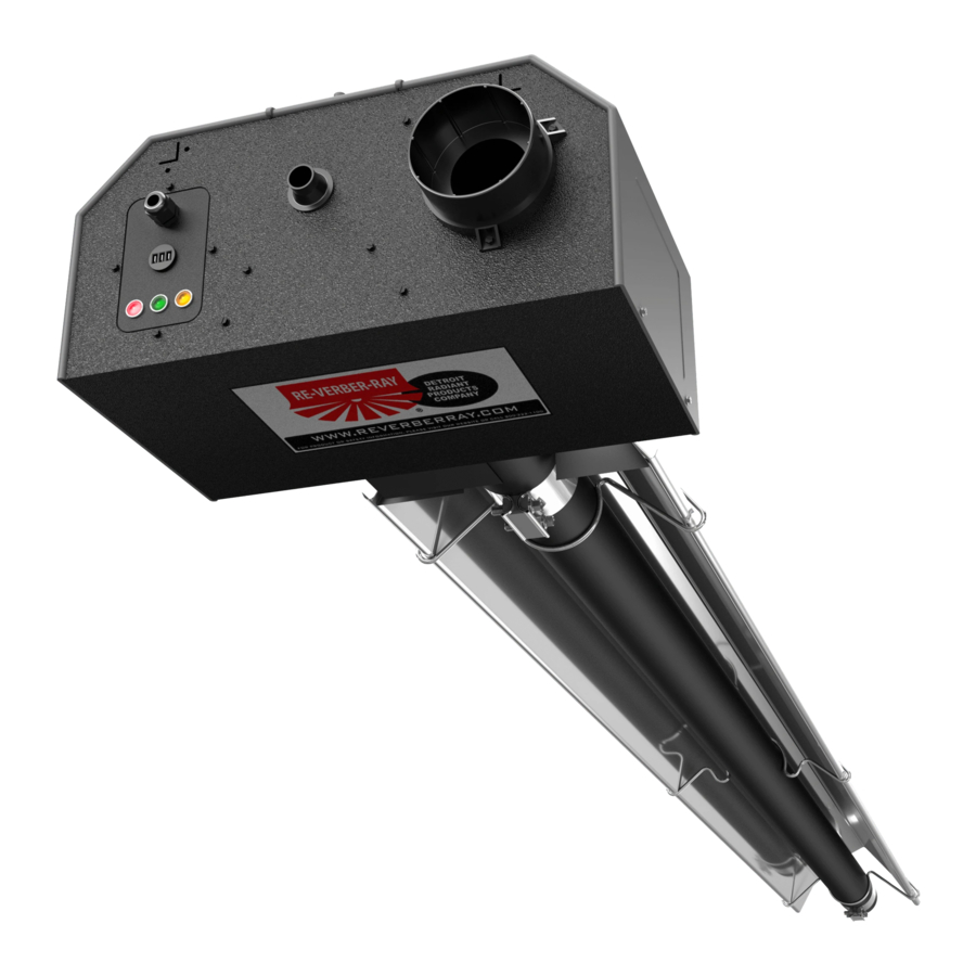
EDX Series
Installation, Operation,
Maintenance, and Parts Manual
CE Certified 230V-50Hz. (G20, G25, G25.3, and G31) Infrared Tube Heater.
The EDX Series Infrared Tube Heater is a positive pressure, single stage radiant heater system. All persons
involved with the installation, operation, and maintenance of the heater system must read and understand the
information in this manual.
Improper installation, adjustment, alteration, service, or maintenance can cause
property damage, injury, or death. Read the installation, operation, and maintenance
instructions thoroughly before installing or servicing this equipment.
This heater must be installed and serviced by a Gas Safe Registered Gas Engineer
only! Conversion of the heater for use with other gases must be carried out by a Gas
Safe Registered Gas Engineer. Failure to comply could result in personal injury,
asphyxiation, death, fire, and/or property damage.
In locations used for the storage of combustible materials, signs must be posted to
specify the maximum permissible stacking height to maintain the required clearances
from the heater to the combustibles. Signs must either be posted adjacent to the
heater thermostats or, in the absence of such thermostats, in a conspicuous location.
For Your Safety
If you smell gas:
• Do not try to light any appliance.
• Do not touch any electrical switch.
• Do not use any phone in your building. • If you cannot reach your gas supplier, call the fire department.
INSTALLER: Present this manual to the end user.
Keep these instructions in a clean and dry place for future reference.
Model#: ___________________ Serial #: _________________________
WARNING
!
• Immediately call your gas supplier from a neighbor's phone.
• Follow the gas supplier's instructions.
(located on rating label)
0063
LIOEDXc-Rev. 08617
Print: 1c-12/20 (DRPC)
Replaces: 1c-03/19 (DRPC)
Advertisement
Table of Contents

Related Manuals for Detroit Radiant Products EDX Series


Summary of Contents for Detroit Radiant Products EDX Series
- Page 1 CE Certified 230V-50Hz. (G20, G25, G25.3, and G31) Infrared Tube Heater. 0063 The EDX Series Infrared Tube Heater is a positive pressure, single stage radiant heater system. All persons involved with the installation, operation, and maintenance of the heater system must read and understand the information in this manual.
-
Page 2: Table Of Contents
Series Contents .0 Introduction............. . . Overview . -
Page 3: Introduction
Series Introduction • • Overview Available Models and Technical Specifications Introduction Overview The intent of this manual is to provide information regarding general safety, installation, operation, and maintenance of this tube heater. You must read and understand all instructions and safety warnings before installing or servicing the tube heater. - Page 4 Series Introduction • Overview • Available Models and Technical Specifications Chart 1.2 • Technical Specifications High Injector Air Inlet Air Inlet Min. Gas Max. Gas Rate Proving Model (Input) Type Injector Marking Orifice Marking Pressure Pressure Pressure Baffle Length by Model Length (m) Set Point (mm) (DMS)
-
Page 5: Safety
Series Safety • Warning Symbols • Applications Safety WARNING Improper installation, adjustment, alteration, service, or maintenance can cause property damage, serious injury, or death. Read and understand the installation, operating, and maintenance instructions thoroughly before installing or servicing this equipment. Only Gas Safe Registered Gas Engineers and service personnel may install or service this equipment, and must do so in accordance with relevant clauses of applicable standards and recommendations. -
Page 6: Codes And Regulations
Series Safety • Codes and Regulations Codes and Regulations The following must be reviewed before installing this heater: • Check the rating label on the heater to verify the proper gas to be used. Check other labels to the heater to verify proper mounting and clearances to combustibles. •... -
Page 7: Clearances To Combustibles
Series Safety • Clearances to Combustibles Clearances to Combustibles WARNING Fire Hazard. Always maintain published clearances to combustibles. Failure to comply with the stated clearances to combustibles may result in personal injury, property damage, and/or death. Failure to mount the appliance level may result in personal injury, property damage, and/or death. -
Page 8: Installation
Series Installation • Clearances to Combustibles IMPORTANT: For the safe installation of this unit, the clearances to combustibles data below contains clearances that must be maintained. Check the rating plate on the heater to verify the minimum clearances to combustibles and gas type for your model heater. -
Page 9: Design Considerations And Prechecks
Series Installation • Design Considerations and Prechecks Installation WARNING Improper installation, adjustment, alteration, service, or maintenance can cause property damage, serious injury, or death. Read and understand the installation, operating, and maintenance instructions thoroughly before installing or servicing this equipment. Only Gas Safe Registered Gas Engineers and service personnel may install or service this equipment. -
Page 10: Recommended Mounting Heights
Series Installation • Recommended Mounting Heights Chart 3.1 • Recommended Mounting Heights Recom- Max. Distance Coverage Coverage Distance Distance Model mended Between Straight U-Tube Between Between Length kW Range Mounting Heaters and Config. Config. Heater Rows Heater Rows Heights Wall (m) Dim. (LxW) (m) (LxW) (m) (m) Dim. -
Page 11: Design Scenarios
Series Installation • Design Scenarios Design Scenarios A tube heater system is being installed in a 27,4 m (L) x 15,2 m (W) space with 4,3 m ceilings. Two overhead doors are located at one end and an equipment storage area exists on one side. The calculated heat load is 85,0 kW. -
Page 12: Hanger Placement And Suspension
Series Installation • Hanger Placement and Suspension Hanger Placement and Suspension WARNING Improper suspension of the radiant tube heater may result in collapse and being crushed. Always suspend from a permanent part of the building structure that can evenly support the total force and weight of the heater. - Page 13 Series Installation • Hanger Placement and Suspension Figure 3.4 • Heater Suspension Layout Suspension Point NOTE: A sticker identifying the combustion chamber(s) is located on the swaged end of the tube(s). Suspension Point Radiant Emitter Tube(s) Suspension Point Radiant Emitter Tube Burner Control Box NOTE: If applicable, use a secondary Suspension Points...
- Page 14 Series Installation • Hanger Placement and Suspension Suspension of the heater must conform to applicable codes referenced in the Safety section and these instructions. Prepare the mounting surface, if necessary, such as weld blocks or drill holes. See Figure 3.5. NOTE: The burner control box and radiant tubes should be in straight alignment and level.
-
Page 15: Radiant Tube Assembly
Series Installation • Radiant Tube Assembly Radiant Tube Assembly To install the radiant tubes: Place tubes in hangers with the welded seam facing downward and the swaged end of the tube towards the exhaust end of the heater system (see Figure 3.6). Refer to page 22 for tube installation sequence. -
Page 16: Optional U-Bend Or Elbow Accessory Configuration
Series Installation • Optional U-Bent or Elbow Accessory Configuration Slip-fit the radiant tube sections together until tightly connected (install swaged end of each tube towards exhaust end). NOTE: If it is difficult to mate the tubes, they may be installed incorrectly. Center tube clamps over the seams where two radiant tube sections connect. - Page 17 Series Installation • Optional U-Bend or Elbow Accessory Configuration NOTE: When installing 9 m, 15 m, and 21 m models in a “U” configuration, the use of a 5EA-SUB accessory package is recommended. Figure 3.10 • U-Tube Hanger Mounting Options Single Mounting Bracket Brass Knuckle...
- Page 18 Series Installation • Optional U-Bend or Elbow Accessory Configuration Elbow can be set Figure 3.12 • Elbow and U-Bend Clearances in both directions Dimension A Tube Clamp Tube Clamp U-Bend can be set in both directions Dimension A 30,5 cm Tube Clamp Tube Clamp 20,3 cm...
-
Page 19: Burner Control Box Suspension
Series Installation • Burner Control Box Suspension Burner Control Box Suspension Suspending the burner control box must be done in accordance with applicable codes listed in the Safety section and these instructions. The burner control box must be in straight alignment with the radiant tubes and level. Determine the mounting chain locations for hanging the burner control box. -
Page 20: Reflector Assembly
Series Installation • Reflector Assembly Reflector Assembly To install the reflectors: Attach reflector center supports onto radiant tubes. Slide each reflector section through the hangers and adjust the reflector tension spring into the V-groove on the top of the reflector. The reflectors should overlap approximately 10 cm. To prevent the reflectors from shifting, secure the reflector sections together using sheet metal screws except at the expansion joint (see page 22). - Page 21 Series Installation • Reflector Assembly Chart 3.6 • Common Optional Accessories Reflector Accessories Description Part # Elbow Reflector* 90° bend, highly polished aluminum reflector elbow designed to fit atop one elbow accessory fitting. U-Reflector* 180° bend, highly polished aluminum reflector U-bend designed to fit atop one U-bend accessory fitting.
-
Page 22: Baffle Assembly And Placement
Series Installation • Baffle Assembly and Placement Baffle Assembly and Placement NOTICE Different inputs and models utilize different baffle lengths. Remove all enclosed baffle sections from box and retain with applicable heater. Reference shipping label, rating label, or the table on page 4 for proper baffle size. - Page 23 Series Installation • Baffle Assembly and Placement To assemble the baffles: NOTE: Baffles may be inserted into the tube while being assembled. Determine the number of baffles needed for your model number. Remove one 84 cm baffle section if heater is installed with an elbow or U-Bend accessory. Install the baffle tabs at a 90°...
-
Page 24: Flueing Requirements
Series Installation • Flueing Requirements Flueing Requirements WARNING Insufficient flueing and/or improperly sealed flues may release gas into the building which could result in health problems, carbon monoxide poisoning, or death. Improper flueing may result in fire, explosion, injury, or death. Seal flue pipes with high temperature sealant and three (3) sheet metal screws. - Page 25 Series Installation • Sidewall (Horizontal) Flueing Sidewall (Horizontal) Flueing Guidelines: • To prevent moisture from entering the heater system, slope the flue pipe down toward the outlet 2 cm per meter of flue length. Do not pitch the heater. • Flue must extend beyond any combustible overhang. Figure 3.21 •...
- Page 26 Series Installation • • Flue Termination Roof (Vertical) Flueing Flue Termination • Always follow all local requirements in the event that they deviate from the information below. • Flue must terminate a minimum of 1,2 m below, 1,2 m horizontally from, and 0,3 m above any window or door that may be opened and gravity air inlet into the building.
- Page 27 Series Installation • Optional Unflued Operation Optional Unflued Operation WARNING Not for residential use. The use of unflued tube heaters in residential indoor spaces may result in property damage, serious injury, or death. Use unflued operation in commercial and industrial installations with proper flueing rates only. When installing in an unflued configuration: •...
-
Page 28: Combustion Air Requirements
Series Installation • Combustion Air Requirements Combustion Air Requirements NOTICE This heater has a factory preset air orifice for proper combustion air supply. If combustion air is to be provided for a tightly closed area, 440 mm free air opening must be provided for each kW of heater input. - Page 29 Series Installation • Combustion Air Requirements Guidelines: Chart 3.7 • Limitations for Length and Size of Combustion Air Intake Duct Single Heater Intake Dual Heater Intake Air Intake Duct Size Max. Intake Length Duct Size Max. Intake 100 mm 6,1 m 150 mm 6,1 m 130 mm...
-
Page 30: Gas Supply And Pressure
Series Installation • Gas Supply and Pressure Gas Supply and Pressure WARNING Improperly connected gas lines may result in serious injury and death, explosion, poisonous fumes, toxic gases, or asphyxiation. Connect gas lines in accordance with national, state, provincial, and local codes. Important! Before connecting the gas supply to the burner control box: •... - Page 31 Series Installation • Adjusting Burner Pressure Adjusting Burner Pressure Remove the lid to the valve compartment. Open the pressure nipple and connect the pressure meter tube. Remove the cap over the adjusting screw on the gas valve pressure regulator. Use the screw to adjust burner pressure. Pressure is increased by turning clockwise. Replace the burner control box lid, then operate the heater to check burner pressure.
-
Page 32: Gas Connection
Series Installation • Gas Connection Gas Connection WARNING Failure to install, operate, or service this appliance in the approved manner may result in property damage, injury, or death. Only Gas Safe Registered Gas Engineers and service personnel may install or service this equipment. To connect the gas: This heater must be installed and service by trained gas installation and service personnel only. - Page 33 Series Installation • Gas Connection WARNING Testing for a gas leak with an open flame or other sources of ignition may lead to a fire or explosion that can lead to serious injury or death. Always test in accordance with local codes.
-
Page 34: Electrical Requirements
Series Installation • Electrical Requirements Electrical Requirements • Verify that the heater’s voltage (as listed on the rating plate) matches that of your application. • Heaters operate on 230 V, 50 Hz., single phase. The maximum amperage requirement is 4.8 A starting current;... -
Page 35: Internal Wiring Diagram
Series Installation • Internal Wiring Diagram Internal Wiring Diagram If any of the original wire as supplied with this appliance must be replaced, it must be replaced with wiring material having a temperature rating of at least 105°C. Figure 3.34 Internal Wiring Diagram •... -
Page 36: Operation
Series Operation • Sequence of Operations Operation WARNING This heater is not equipped with a pilot ignition system. Do not attempt to light the system manually. Commissioning Procedures: Ensure that ball valve to the heater is turned “OFF”. Purge air from the gas supply line and test for gas soundness in accordance with relevant standards. Check that all electrical connections are made to the heater and that the unit has a sound earth connection. -
Page 37: Maintenance
Do not operate unit if repairs are necessary. Maintenance Checks EDX Series gas-fired infrared heaters require minimum routine maintenance to keep them operating at peak performance. The inspection shall be performed annually by trained gas installation and service personnel. It is recommended that this inspection is performed before the beginning of the heating season to help ensure all heater components are in proper working order and the heating system functions appropriately. -
Page 38: Converting Heaters From One Gas Type To Another
Series Maintenance • Converting Heaters from One Gas to Another Converting Heaters from One Gas to Another • Conversions Table 5.2 Suitable Gas Supply Marking Gas Type Pressure Country of Use Notes United Kingdom, Ireland, Austria, Denmark, Finland, Natural 20 mbar Suitable for use without modification. - Page 39 Series Maintenance • Converting Heaters from One Gas to Another Converting a Heater from Natural Gas (I2H) to LPG (I3P) If the heater is already installed, switch the gas and electricity OFF, then remove the heater to the ground level. Remove the injectors.
- Page 40 Series Maintenance • Converting Heaters from One Gas to Another Converting a Heater for Operation on Group LL Nat. Gas (I2ELL) in Germany Follow the procedure outlined on the previous page for conversion of a heater for operation on natural gas. Replace the injectors with the correctly sized injectors for Group LL Natural Gas (see Chart 1.2).
-
Page 41: Troubleshooting Guide
Series Maintenance • Troubleshooting Guide Troubleshooting Guide Chart 5.2 • Troubleshooting Guide Symptom Possible Cause Corrective Action Thermostat closed, fan doesn’t • Blown fuse • Replace operate • Faulty thermostat • Replace • Loose or disconnected wire • Repair as required •... -
Page 42: Parts
Series Parts • Burner Assembly Components Parts Figure 6.1 • Burner Assembly Components 664D, 664E, 3625 664F 3651A 3083 628A,B,C 656A 3055 3652A 646A 201B, 3072, 3571 740A 208B Table 6.1 • Parts List Part # Description TP-1 Control Box Cover TP-65I Interlocking 838 mm Baffle Section TP-5... -
Page 43: Tube And Reflector Components
Series Parts • Tube and Reflector Components Figure 6.2 • Tube and Reflector Components 20C,D 26A, 26D 21B, 220 26A,B,C,E Table 6.2 • Parts List (continued) Part # Description TP-220 101 mm Stainless Steel Tube Clamp TP-656A Ignition Filter TP-223 Gas Manifold TP-664D Pressure Switch (Consult Factory) -
Page 44: Kit Contents
Reflector End Caps Reflector End Caps Clips The EDX Series Infrared Tube Heater is a positive pressure, single stage radiant heater system. All persons involved with the installation, operation, and maintenance of the heater system must read and understand the information in this manual.
Need help?
Do you have a question about the EDX Series and is the answer not in the manual?
Questions and answers