Table of Contents
Advertisement
Quick Links
Advertisement
Table of Contents

Subscribe to Our Youtube Channel
Related Manuals for Element CA850


Summary of Contents for Element CA850
- Page 1 USER MANUAL VERSION 1.01 November 2020 CA850 Hardware System...
- Page 2 Copyright 2020 All Rights Reserved Manual Version 1.0 The information contained in this document is subject to change without notice. We make no warranty of any kind with regard to this material, including, but not limited to, the implied warranties of merchantability and fitness for a particular purpose. We shall not be liable for errors contained herein or for incidental or consequential damages in connection with the furnishing, performance, or use of this material.
- Page 3 CE MARK This device complies with the requirements of the EEC directive 2014/30/EU with regard to “Electromagnetic compatibility” and 2014/35/EU “Low Voltage Directive”. This device complies with part 15 of the FCC rules. Operation is subject to the following two conditions: (1) This device may not cause harmful interference.
- Page 4 LEGISLATION AND WEEE SYMBOL 2012/19/EU Waste Electrical and Electronic Equipment Directive on the treatment, collection, recycling and disposal of electric and electronic devices and their components. The crossed dust bin symbol on the device means that it should not be disposed of with other household wastes at the end of its working life.
- Page 5 Revision History Changes to the original user manual are listed below: Revision Description Date • Initial release November 2020...
-
Page 6: Table Of Contents
Table of Contents 1. Packing List ......... 1 1-1. Standard Accessories ............. 1 1-2. Optional Accessories ............2 2. System View ......... 3 2-1. Front & Side View ............3 2-2. Rear View ................. 3 2-3. IO Ports View ..............4 2-4. - Page 7 The page is intentionally left blank.
-
Page 9: Packing List
Packing List 1-1. Standard Accessories System Power adapter (90W) Power cord RJ45-DB9 cable (x2) Note: Power cord will be supplied differently according to various region or country. -
Page 10: Optional Accessories
1-2. Optional Accessories a. MSR module g. 11.6" or 15.6" 2 display b. NFC module h. Hinge cover for 2 display c. iButton module Arm cover for 2 display (Top) d. Fingerprint Arm cover for 2 display (Bottom) x 2 e. -
Page 11: System View
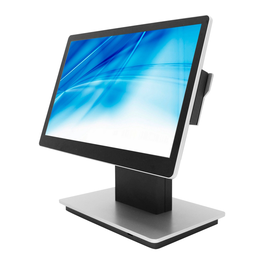
System View 2-1. Front & Side View Description Touch screen USB2.0 Power button Hinge cover Stand arm Stand arm cover Stand front cover 2-2. Rear View Description Dummy door of MSR/iButton module Power/OSD button System box... -
Page 12: Io Ports View
2-3. IO Ports View Description FeDP (2 display) DC 19V in USB 2.0 x 2 USB Type C x 2 USB 3.0 x 2 COM x 2 Cash drawer FeDP (Main display) 2-4. System Dimensions 368.8mm 200mm... -
Page 13: System Assembly & Disassembly
System Assembly & Disassembly Install the Power Adapter 3-1. The system is equipped with a 90W power adapter. Please plug it into the system as shown below. 1. Find the DC-in connector located on the bottom of the system.(refer to Chapter 2-3). - Page 14 3. Disconnect the cable of the LCD panel. 4. The system box is placed onto four hooks. Lift the system box and then pull it outwards to release it from the bottom of the stand.
-
Page 15: Peripherals Installation
Peripherals Installation Install the MSR/ NFC/ iButton/ Fingerprint Module 4-1. 1. The variety of peripherals MSR, NFC, iButton, and Figerprint modules can be installed to each side of the system depends on your preference. 2. Press to remove the dummy cover and then loosen the screws (x2). 3. -
Page 16: Install The Customer Display
Install the Customer Display 4-2. 1. To install the customer display, replace the hinge cover with the one which has a opening in the top. Removing the hinge cover: The cover attaches magnetically to the hinge. Pull the top side of the cover ourdwards frst and then release the rest part of the cover to seperate it from the hinge. -
Page 17: Install The Second Display
4-3. Install the Second Display Accessories items a. 11.6" or 15.6" 2 display module b. Top arm cover Bottom arm cover d. Hinge cover e. Screws for 2 display arm x 5 Screws for top arm cover x 4 Screws for bottom arm cover x 2 1. - Page 18 5. Secure the top arm cover by fastening the screws (x4) from underneath. 6. Attach the bottom arm covers (x2) and fasten the screws (x2). 7. Follow steps 1 and 2 described in Chapter 3-2 to release the holder of the system box.
-
Page 19: Cash Drawer Installation
4-4. Cash Drawer Installation You can install a cash drawer through the cash drawer port. Please verify the pin assignment before installation. Cash Drawer Pin Assignment Signal Cash drawer 2 In Cash drawer 1 Out Cash drawer 1 In 12V / 19V Cash drawer 2 Out Cash Drawer Controller Register The Cash Drawer Controller use one I/O addresses to control the Cash Drawer. - Page 20 Bit 7: Reserved Bit 6: Reserved Bit 5: Reserved Bit 4: Cash Drawer 1 pin output control. = 1: Opening the Cash Drawer = 0: Allow close the Cash Drawer Bit 3: Cash Drawer 1 pin input control. = 1: the Cash Drawer closed or no Cash Drawer = 0: the Cash Drawer opened Bit 2: Reserved Bit 1: Reserved...
-
Page 21: Specification
Front: 1x USB2.0 1 x full-functional, PDO 5V@3A / PDO 12V@1.5A / PDO 20V@1A 1 x data only, PDO 5V@3A / PDO 19V@5A (for Element powered USB board, E- USB Type C Mark required on cable) (90W adapter cannot support 19V@5A on this port,... - Page 22 Model Name CA850 Mainboard D84U Power Power adapter default 19V/90W, 120W with powered USB box Peripherals (optional) 1 (USB) Fingerprint 1 (USB) iButton 1 (USB) NFC card reader 1 (USB) 2D scanner 1 (USB) Second display 11,6” or 15.6" 2...
-
Page 23: Configuration
SW1/ CN18 FAN1 USB1 CN20 CN16 CN10 CN11 DOMM_A1 JP2 JP6 CN13 CN17 CN14 CN7 JP3 USB5 FeDP2 RJ45_1 USB4 USB8 USB2 USB3 RJ11_1 FeDP1 USB7 CN12 PWR1/ COM2 COM1 PWR2... -
Page 24: Connectors & Functions
6-2. Connectors & Functions Connector Function EC Debug SATA power connector M.2 E-KEY WIFI connector CN4/11 M.2 M-KEY PCIE/SATA connector Speaker R output S0/S5 LED & power button connector Storage LED connecotr CN9/CN10/CN12/CN14 Internal USB connector CN16 RTC battery Connector CN17 Wide range &... -
Page 25: Jumper Setting
6-3. Jumper Setting Audio Line-out Setting Function _.Stereo Reserved (line-out) Cash Drawer Power Setting Function _. +19V +12V Speaker Watt Setting Function _.3W Speaker Cable Setting Function _. L=0.58m L=2.0m... - Page 26 LCD ID Setting To set the panel ID, please insert the jumper on the FeDP to LVDS board. Panel# Resolution JP1 JP2 Reserved 800 x 600 800 x 600 1024 x 768 1024 x 768 1366 x 768 1366 x 768 CN10 1024 x 600 1280 x 1024...
- Page 27 Panel Backlight Current Setting JP1 JP2 LED current 200mA 240mA 280mA 320mA 360mA 400mA 420mA CN10 460mA CN11 500mA CN12 Jumper open Jumper short...
- Page 28 COM1/COM2 Power Setting COM1, COM2 can be set to provide power to your serial device. The voltage can be set to +5V or +12V in the BIOS. 1. Power on the system, and press the <DEL> key when the system is booting up to enter the BIOS Setup utility.
Need help?
Do you have a question about the CA850 and is the answer not in the manual?
Questions and answers