Table of Contents
Advertisement
Quick Links
Advertisement
Table of Contents

Related Manuals for Element CA250W


Summary of Contents for Element CA250W
- Page 1 CA250W User Manual Rev 1.2 www.elementpos.co...
- Page 2 FCC Information and Copyright This equipment has been tested and found to comply with the limits of a Class B digital device, pursuant to Part 15 of the FCC Rules. These limits are designed to provide reasonable protection against harmful interference in a residential installation.
-
Page 3: Table Of Contents
Table of Contents 1. Introduction ..................4 2. Specification ..................5 2.1 CPU Support ........................5 2.2 Memory ..........................5 2.3 Main Screen ........................5 2.4 Touch Panel ........................5 2.5 Storage ..........................5 2.6 I/O Ports..........................5 2.7 Model Features ......................... 6 2.8 OS Support ........................ - Page 4 3.2 VFD 2x20 Columns (Optional) ..................10 3.2.1 Specification ......................10 3.2.2 Input ........................10 3.2.3 Operating Environment ................... 10 3.3 MSR (Optional) ....................... 10 3.4 Power Supply ........................11 3.4.1 Power Adaptor Specification ................... 11 4. Installation ..................12 4.1 SSD Installation .......................
-
Page 5: Introduction
Sharp pins on headers and connectors. ⚫ Rough edges and sharp corners on the chassis. ⚫ Damage to wires that could cause a short circuit. Package List ◼ Element CA250W x1 (Power Adaptor and Power Cord are Included) ◼ RJ to COM Cable x 2... -
Page 6: Specification
2. SPECIFICATION 2.1 CPU Support ◼ Product Collection: Intel® Celeron Processor J Series ◼ Code Name: BayTrail ◼ Processor: J1900 ◼ Processor Base Frequency: 2.00 GHz ◼ Burst Frequency: 2.42 GHz ◼ Cache: 2 MB 2.2 Memory ◼ 1 X 204-pin DDR3L SO-DIMM socket 1333/1600Mhz up to 8GB 2.3 Main Screen ◼... -
Page 7: Model Features
2.7 Model Features (Optional) ◼ Magnetic Strip Reader Track 1,2,3. ◼ Vacuum Fluorescent Display (VFD) with Display 20 Columns and 2 lines. ◼ 10.1” 2 Display 2.8 OS Support ◼ POSReady 7 ◼ Windows 10 IOT 2.9 Voltage Input 12 VDC/5A ◼... -
Page 8: Software/Peripherals
2.16 Software/Peripherals ◼ OPOS ◼ ◼ Cash Drawer ◼ Customer Display (VFD) ◼ Thermal Printer (Optional) -
Page 9: Terminal Overview / Components
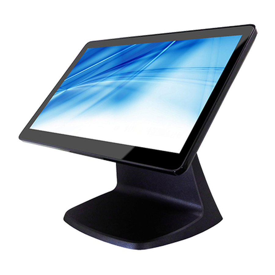
3. TERMINAL OVERVIEW / Components 3.1 Appearance The Element CA250W complete configuration is pictured below. The Element CA250W includes a projected capacitive touch screen with true flat touch. The design provides an accurate surface touch. ◼ LED light will be on when booting. -
Page 10: Power Switch
3.1.1 Power Switch ◼ ower switch is located on the left I/O port side of 15.6” main screen 3.1.2 User Accessible Interface ◼ I/O Ports as Below 1. Power Switch (PWRBTN1) 7. RJ11 Port (RJ11) 2. DC Jack Port (DC_JACK1) 8. -
Page 11: Installation Option
◼ Magnetic Strip Reader (MSR) ◼ Customer Display (VFD / 2 Display) ◼ Solid-state Disk (SSD) 3.1.5 Installation Option ◼ Pedestal stand ◼ Wall mount 3.1.6 Operating Environment ◼ Celsius 0°C ~ 40°C, Humidity 15% RH ~ 80% RH 3.2 VFD, 2x20 Columns (Optional) 3.2.1 Specification ◼... -
Page 12: Power Supply
3.4 Power Supply 3.4.1 Power Adaptor Specification ◼ Input Voltage: 100V ~ 240 VAC, 50 ~ 60Hz, Auto-Ranging ◼ Nominal Output Voltage: 12V ◼ Rated Output Current: 5A ◼ Rated Power: 60W ◼ MTBF: 50,000 hours... -
Page 13: Installation
4. INSTALLATION 4.1 SSD Installation Step 1. Remove the right-side cover. Step 2. Draw the SSD/HDD out to replace it. After swapping the SSD/HDD and reinsert the cover. -
Page 14: Msr Installation
4.2 MSR Installation Step 1. Remove the left side cover. Step 2. Attach the cable’s connectors together. Step 3. Tighten two screws on the MSR. -
Page 16: Customer Display
4.3 Customer Display: VFD Type Step 1: Remove the top cover. Step 2: Connect the interface cable. Step 3: Install the holder bracket and tighten two screws on each side of the bracket. 4.4 Customer Display: 10.1” Step 1: Remove the top cover. - Page 17 Step 2: Connect the interface cable. Step 3: Install the holder bracket and tighten two screws on each side of the bracket. Step 4: Correct the touch screen calibration 1. Power the system on, connect a mouse and launch the iUniTouch tool. 2.
-
Page 19: Bios Setup
5. BIOS Setup 5.1 Main BIOS Information This section explains how to use the UEFI SETUP UTILITY to configure your system. The UEFI chip on the motherboard stores the UEFI SETUP UTILITY. You may run the UEFI SETUP UTILITY when you start up the computer. Please press <F2> or <Del> during the Power-On-Self-Test (POST) to enter the UEFI SETUP UTILITY, otherwise, POST will continue with its test routines. -
Page 20: Navigation Keys
5.1.2 Navigation Keys 5.2 Main Screen When you enter the UEFI SETUP UTILITY, the Main screen will appear and display the system overview. -
Page 21: Advanced Screen
5.3 Advanced Screen In this section, you may configure the following items: CPU, Chipset, Storage, Super IO, ACPI and USB. Setting incorrect values in this section may cause system instability. Please proceed with caution. Instant Flash Instant Flash is a UEFI flash utility embedded in Flash ROM. This convenient UEFI update tool allows you to update system UEFI without entering operating systems first like MS-DOS or Windows®. -
Page 22: Cpu Configuration
5.3.1 CPU Configuration Intel SpeedStep Technology Intel SpeedStep technology is Intel’s new power saving technology. Processors can switch between multiple frequencies and voltage points to enable power saving. The default value is [Enabled]. If you install Windows® 7 / 8 / 8.1 and want to enable this function, please set this item to [Enabled]. -
Page 23: Chipset Configuration
5.3.2 Chipset Configuration Active LVDS Use this to enable or disable the LVDS. The default value is [Disabled]. Panel Type Selection This option appears only when you enable Active LVDS. Onboard LAN 1 This allows you to enable or disable the Onboard LAN 1 feature. Deep S5 This allows you to enable or disable Deep S5. -
Page 24: Storage Configuration
5.3.3 Storage Configuration SATA Controller(s) Use this item to enable or disable the SATA Controller feature. SATA Mode Selection Use this to select SATA mode. Configuration options: [IDE Mode] and [AHCI Mode]. The default value is [AHCI Mode]. AHCI (Advanced Host Controller Interface) supports NCQ and other new features that will improve SATA disk performance, IDE mode does not have these advantages. -
Page 25: Super Io Configuration
5.3.4 Super IO Configuration COM1 Configuration Use this to set parameters of COM1. COM2 Configuration Use this to set parameters of COM2. COM3 Configuration Use this to set parameters of COM3. COM4 Configuration Use this to set parameters of COM4. WDT Timeout Reset This allows users to enable/disable the Watch Dog Timer timeout to reset system. - Page 26 5.3.5 ACPI Configuration Suspend to RAM Use this item to select whether to auto-detector disable the Suspend-to- RAM feature. Select [Auto] will enable this feature if the OS supports it. PCIE Devices Power On Use this item to enable or disable PCIE devices to turn on the system from the power-soft-off mode.
-
Page 27: Usb Configuration
5.3.6 USB Configuration Intel USB 3.0 Mode Select Intel® USB 3.0 controller mode. Set [Smart Auto] to keep the USB 3.0 driver enabled after rebooting (USB 3.0 is enabled in BIOS). Set [Auto] to automatically enable the USB 3.0 driver after entering the OS (USB 3.0 is disabled in BIOS). -
Page 28: Hardware Health Event Monitoring Screen
5.4 Hardware Health Event Monitoring Screen Monitor the status of the hardware on your system, including the parameters of the CPU temperature, motherboard temperature, CPU fan speed, chassis fan speed, and the critical voltage. CPU_FAN1 Setting This allows you to set CPU fan 1’s speed. Configuration options: [Full On] and [Automatic Mode]. -
Page 29: Security Screen
5.5 Security Screen Set, change or clear the supervisor/user password for the system. Supervisor Password Set or change the password for the administrator account. Only the administrator has authority to change the settings in the UEFI Setup Utility. Leave it blank and press enter to remove the password. User Password Set or change the password for the user account. -
Page 30: Boot Screen
5.6 Boot Screen Display the available devices on your system for you to configure the boot settings and the boot priority. Fast Boot Fast Boot minimizes your computer’s boot time. There are three configuration options: [Disabled], [Fast] and [Ultra Fast]. The default value is [Disabled]. Please refer to below descriptions for the details of these three options: [Disabled] - Disable Fast Boot. - Page 31 Bootup Num-Lock If this item is set to [On], it will automatically activate the Numeric Lock function after boot-up. Boot Beep Select whether the Boot Beep should be turned on or off when the system boots up. Full Screen Logo Use this item to enable or disable OEM Logo.
- Page 32 Launch Storage OpROM Policy Select UEFI only to run those that support UEFI option ROM only. Select Legacy only to run those that support legacy option ROM only. Select Do not launch to not execute both legacy and UEFI option ROM. Launch Video OpROM Policy Select UEFI only to run those that support UEFI option ROM only.
-
Page 33: Exit Screen
5.7 Exit Screen Save Changes and Exit When you select this option, it will pop-out the following message, “Save configuration changes and exit setup?” Select [OK] to save the changes and exit the UEFI SETUP UTILITY. Discard Changes and Exit When you select this option, it will pop-out the following message, “Discard changes and exit setup?”...
Need help?
Do you have a question about the CA250W and is the answer not in the manual?
Questions and answers