
Related Manuals for Kärcher HDC Series


Summary of Contents for Kärcher HDC Series
- Page 1 HDC Series Planning Manual SWEEPEX AUSTRALIA 1800 680 337 www.sweepex.com.au sales@sweepex.com.au 5.962-786.0...
- Page 2 Basics of Cleaning ......... . . 1.1 Cleaning circuit .
- Page 3 4.3.5 Overflow valve with flow switch ......4.3.6 Pressure sensor for high pressure ......4.4 Specifications sheet .
- Page 4 5.5.8 Turn off the appliance........5.6 Shutdown .
- Page 5 7.8.3 High-pressure hoses for hose reel ......7.8.4 High-pressure hose connections (connection M 22x1.5 mm) ..7.8.5 Hand spray guns .
- Page 6 Basics of Cleaning Kärcher offers a complete programme of high-perfor- For the high-pressure cleaning of a surface seven mance stationary high-pressure cleaning systems as factors are effective. These are depicted in the high- systematic problem solutions: pressure circuit. The perfect technology is completed with the correct accessories, proper detergents, application know- how, and reliable service.
- Page 7 1.1.1 Impact pressure To loosen a dirt particle, the impact force is less im- portant than the impact pressure, i.e. the impact force per surface unit. This is the pressure, with which the water jet hits the surface to be cleaned. The impact pressure depends on the spray distance, spray angle, nozzle pressure and delivery rate.
- Page 8 1.1.2 Influences on the impact pressure Influence of the spray distance on the impact pres- sure: Aufpralldruck (bar) Düsendruck 80 bar Spritzwinkel 25° 0,15 unüblicher Spritzabstand 0,10 x-axis = spray distance in cm y-axis = impact pressure in bar Deutsch 5.962-786.0 Rev. 05 (06/13)
- Page 9 Influence of the spray angle on the impact pressure: 0,15 0,10 x-axis = spray angle y-axis = impact pressure in bar Deutsch 5.962-786.0 Rev. 05 (06/13)
- Page 10 Influence of the nozzle pressure on the impact pres- sure: Aufpralldruck (bar) Spritzabstand 20 cm Spritzwinkel 25° optimaler Bereich 500 l/h Düsendruck (bar) 500 l/h 750 l/h 900 l/h 1200 l/h Motorleistung (kW) Deutsch 5.962-786.0 Rev. 05 (06/13)
- Page 11 1.1.3 Limits of the impact pressure 1.1.5 Limits of the water volume The upper limited is given if material damage occurs Minimum: approx. 700 l/h; with smaller values, the during cleaning. Therefore, the impact pressure is jet will open too much even with low pump pressure, determined by the type of surface to be cleaned.
- Page 12 When using detergents, the safety information on the Detergent safety data sheet and on the detergent label must be In addition to the water volume and the water temper- observed. ature, detergents play an important role in high-pres- Because of the materials used in the high-pressure sure cleaning, comparable to the washing machine cleaning systems, the following detergent types must process.
- Page 13 Floor clean- Food industry/disassembly Intensive basic cleaner RM 750 1-5% facilities Floor basic cleaner RM 69 0,5-1% Beverage facilities/wine Intensive basic cleaner RM 750 1-5% cellars, community Floor basic cleaner RM 69 0,5-1% Automotive/lorry workshop Intensive basic cleaner RM 750 1-5% Floor basic cleaner RM 69...
- Page 14 Stationary high-pressure cleaners With the HDC Advanced systems a frequency Advantages of stationary high-pres- converter controls the water volume at a pump de- sure cleaners pending on the consumption volume. For many cleaning tasks, a stationary high-pressure The extracted water volume is monitored by means cleaner can be used.
- Page 15 Innovative pump technology 1 Low-wear stainless steel piston 14 High-strength, forged cylinder head made of cor- rosion-resistant special alloy ECO-brass 2 Improved suction performance and low pressure losses by optimised stream cross sections. ECO-brass (lead free, food grade) is a special brass 3 Guide bar with large diameter and reduced friction alloy.
- Page 16 HDC Classic High-pressure support unit for central supply of Functions: cleaning systems with any number of access points. Automatic switch-on via activation of a hand spray For the operation of max. 2 hand spray guns at the same time with a maximum delivery rate of 2000 l/ Unpressurised circulation the water volume not re- ...
- Page 17 Specifications of the four configurable HDC Classic models HDC Classic Unit HDC 20/8 HDC 20/8 H HDC 20/16 HDC 20/16 H Flow rate 2000 2000 2000 2000 Pressure bar/Mpa 80/8 80/8 160/16 160/16 input temperature °C Connected load Voltage Current type Ph/Hz 3~/50 3~/50...
- Page 18 Function 3.2.1 Flow pattern 1 Locking tap (onsite) 2 Temperature sensor 3 Water shortage safeguard 4 Float tank 5 Advance pressure pump (Option) 6 Crankshaft pump 7 Safety valve 8 Electro motor 9 Pressure switch (HDC 20/16 only) 10 Manometer 11 Pressure sensor 12 Overflow valve 13 Float valve, with the hot water version made of...
- Page 19 3.2.2 Water inlet 3.3.2 Temperature sensor The water flows back from the swimmer tank to the The temperature sensor switches off the appliance suction side of the pump. The water level in the swim- as soon as the water temperature is too high. mer tank is kept constant by the swimmer valve.
- Page 20 4 HDC 20/16 Flow diagram 1 1 Consumer 1/ nozzle 1 2000 l/h, 160 bar, max. 2 extraction points at the 1000 l/h, 100 bar same time 2 Consumer 2/ nozzle 2 5 Overflow valve 1000 l/h, 100 bar Threshold 105 bar 3 System pressure: 100 bar Flow diagram 2 1 Consumer 1/ nozzle 1...
- Page 21 3.3.6 Pressure sensor If the hand spray gun is opened again, the pressure switch switches on the pump via the pressure sensor. 3.3.7 General faults When one of the above mentioned errors is triggered, the operation readiness of the system is switched off and the pump is shut down.
- Page 22 Dimension sheet A High pressure connection (DN 15 - M22x1.5) B Water connection (3/4“, flat-sealing) Deutsch 5.962-786.0 Rev. 05 (06/13)
- Page 23 Sample installation HDC Classic A Water inlet G 3/4" 10 HD hose, DN 12, operating pressure 160 bar, L=1,500 mm, max. temperature 125 , smallest B High pressure output M 22x1.5 bending radius 175 mm, M 22x1.5 C Overflow / water tank Order no.
- Page 24 HDC standard High pressure supply unit for the central supply of high pressure cleaning systems with any number of Automatic start via activation of gun extraction locations. Return of the non-extracted water volume in partial load operation via central overflow valve to the ad- For the simultaneous operation of 2 to 8 lances with a ...
- Page 25 Specifications of the configurable HDC standard models HDC 40/8 HDC40/8H HDC 60/8 HDC60/8H HDC 80/8 HDC80/8H Performance data Working pressure 8 (80) 8 (80) 8 (80) 8 (80) 8 (80) 8 (80) (bar) Max. excess oper- 13 (130) 13 (130) 13 (130) 13 (130) 13 (130)
- Page 26 Optional accessories VA frame Steel panels VA panels Floor structure included in the scope of delivery possible accessories - Accessories not available *temperature sensor PT 100 (6.375-485.0) is set to 68°C in the software. HDC 40/8 HDC40/8H HDC 60/8 HDC60/8H HDC 80/8 HDC80/8H Performance data Working pressure...
- Page 27 3,63 3,63 3,63 3,63 7,52 7,52 7,52 7,52 Optional accessories VA frame Steel panels VA panels Floor structure included in the scope of delivery possible accessories - Accessories not available *temperature sensor PT 100 (6.375-485.0) is set to 68°C in the software. Deutsch 5.962-786.0 Rev.
- Page 28 Function 4.2.1 Flow pattern 1 Dirt catcher (at the site) 10 High pressure hose 2 Temperature sensor 11 Pressure sensor for high pressure 3 Water shortage safeguard 12 Overflow valve 4 Float tank 13 Flow switch 5 Advance pressure pump 14 Swimmer valve (Option) 15 Locking tap (onsite)
- Page 29 4.2.2 Water inlet Safety Devices The water flows back from the swimmer tank to the Safety devices serve for the protection of the user suction side of the pump. The water level in the swim- and must not be put out of operation or bypassed with mer tank is kept constant by the swimmer valve.
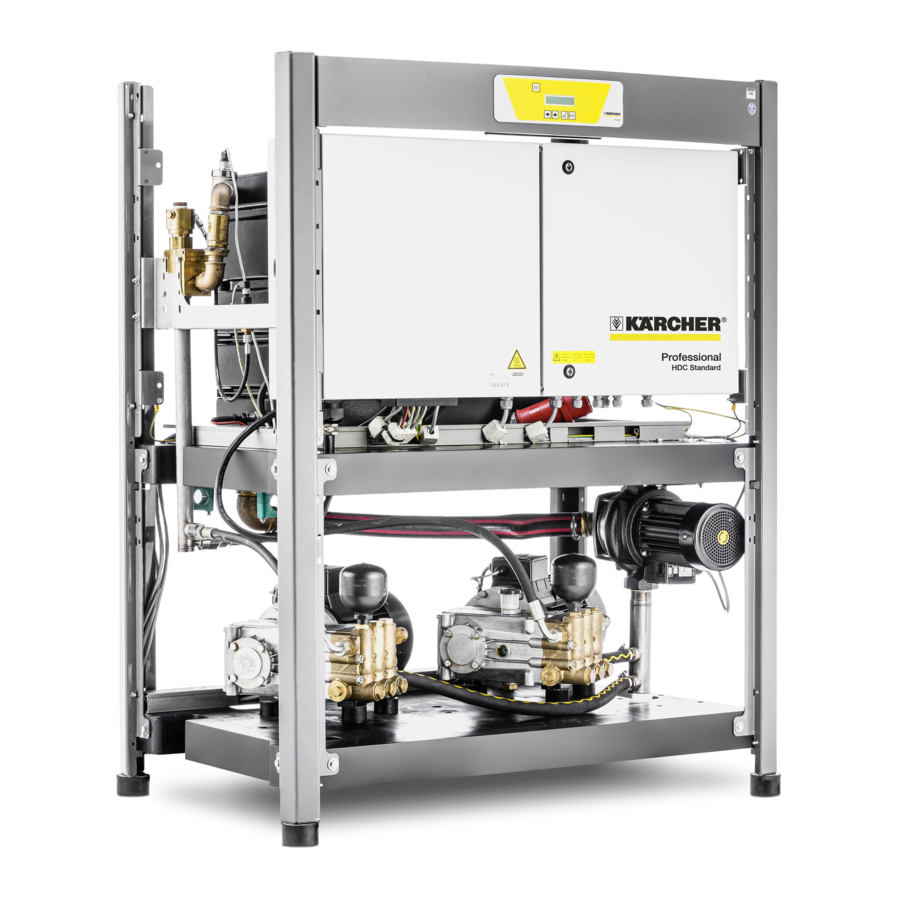
- Page 30 Specifications sheet Illustration HDC 80/16 H without metal panels A High pressure connection B Water connection C Connecting the mains cable D Minimum wall distance Deutsch 5.962-786.0 Rev. 05 (06/13)
- Page 31 Sample installation HDC Standard *) included in the standard scope of delivery (SL) Note Gradient differences can be compensated by means of telescopic feet. Deutsch 5.962-786.0 Rev. 05 (06/13)
- Page 32 4000 litres model 8 Socket, DN 32, G 1 1/4" A Water inlet G1 1/4" Order no. 6.385-246.0 B High pressure output M 30x1.5 8000 litres model C Overflow water tank A Water inlet G1 1/2" 1 HD hose, DN 32, G 1 1/4", operating pressure B High pressure output M 30x1.5 45 bar, max.
- Page 33 Functional description of the HDC standard control Leakage in the area of small extraction volumes 4.6.1 Basic functions With small leakage amounts, the pump starts and af- The "ON" button switches the device into the ready ter a very short time, the entire water volume flows mode, the lamp "Ready"...
- Page 34 4.6.9 Temperature monitoring - engine and en- 4.6.11 Operating hour counter gine protection switch The run time of the high-pressure pump is deter- The engine of the pumps is equipped with a winding mined and saved. The current value of the pumps is protection contact.
- Page 35 4.6.16 Basic display 4.6.17 Fault codes Error Error description Error number type Control voltage is missing Display, no communication Motor protection switch high pressure pump 1 Motor protection switch high pressure pump 2 A Device ready Display of the current system pressure and alter- Motor protection switch high nating operating time and the operating status of pressure pump 3...
- Page 36 Fault Possible cause Remedy of whom Appliance is not running There is no voltage in the ma- Check electrical mains. Electrician chine. Motor protection switch for the Check motor protection switch. Customer control has been triggered. Service Error code 01 is dis- Control board defective, green Check control board, replace if Customer...
- Page 37 Fault Possible cause Remedy of whom Error code 42 is dis- Leakage in the high-pressure Locate and seal leakage. Operator played pipeline system. Too many consumer loads Close some consumer loads. Operator open at the same time. Pressure sensor for high pres- Replace pressure sensor.
- Page 38 HDC Advanced High pressure supply unit for the central supply of Automatic start via activation of gun high pressure cleaning systems with any number of Partial quantity regulation by regulating the water extraction locations. volume at a pump vie the freqency transducer For the simultaneous operation of 2-17 lances with ...
- Page 39 Specifications of the configurable HDC advanced models HDC 60/10 HDC 90/10 HDC 120/ HDC 60/10 HDC 90/10 HDC 120/ Advanced Advanced 10 Ad- H Ad- H Ad- 10 H Ad- vanced vanced vanced vanced Performance data Working pressure MPa 10 (100) 10 (100) 10 (100) 10 (100)
- Page 40 Machine vibrations Vibration total val- ue (ISO 5349) Hand spray gun 3,63 3,63 3,63 3,63 3,63 3,63 Spray lance 7,52 7,52 7,52 7,52 7,52 7,52 Optional accessories VA frame Steel panels VA panels Floor structure included in the scope of delivery possible accessories - Accessories not available Deutsch 5.962-786.0 Rev.
- Page 41 Function 5.2.1 Flow pattern 1 Dirt catcher (at the site) 10 High pressure hose 2 Temperature sensor 11 Pressure sensor for high pressure 3 Water shortage safeguard 12 Overflow valve 4 Float tank 13 Flowmeter 5 Advance pressure pump 14 Swimmer valve (Option) 15 Locking tap (onsite) 6 Crankshaft pump...
- Page 42 5.2.2 Water inlet Safety Devices The water flows back from the swimmer tank to the Safety devices serve for the protection of the user suction side of the pump. The water level in the swim- and must not be put out of operation or bypassed with mer tank is kept constant by the swimmer valve.
- Page 43 – Risk of accident on account of damage! Clean Start up tyres and valves from a minimum distance of 30 Danger Risk of injury! Device, tubes, high pressure hose and Danger connections must be in faultless condition. Other- Danger from substances that are harmful to health! wise, the appliance must not be used.
- Page 44 5.5.3 Display 5.5.4 Making the plant ready for operations Note Danger The text is shown in English. Risk of injury on account of the emanating water jet that could be hot! Danger Check the high pressure hose for damage before every use.
- Page 45 Specifications sheet Illustration HDC 120/12 without metal panels A High pressure connection Surface B Water connection Height C Minimum wall distance D Space requirements for switch cabinet Deutsch 5.962-786.0 Rev. 05 (06/13)
- Page 46 Sample installation HDC Advanced *) included in the standard scope of delivery (SL) Deutsch 5.962-786.0 Rev. 05 (06/13)
- Page 47 6000 litres model HD ball valve, DN 32, G 1 1/4", PN 400, internal A Water inlet G1 1/4", DN32 thread, stainless steel, order no. 6.413-501.0 B High pressure output M 30x1.5 alternatively: C Overflow water tank 7 Bushing, DN 32, G 1 1/4", PN 160, interior thread, zinc-plated D Connecting cable 5 m Order no.
- Page 48 Planning of the complete system / line network When planning HDC installations many important 6.5.4 Detergent supply factors must be considered. The following guidelines 6.5.5 Purpose and function of overflow valves and regulations must be observed upon planning and installation: Ascertainment of data required for the VDMA standard sheet 24416, fixed high-pressure ...
- Page 49 6.1.3 Which pressure area is required? pH value 6,5..9,5 HDC XX/08 60-80 bar electrical conductivity < 2,000 μS/cm HDC XX/16 80-160 bar removable materials < 0.5 mg/l HDC XX/10 60-100 bar filterable materials (parti- < 20 mg/l cle size < 0.025 mm) Based on the three pieces of information already ob- tained the suitable HDC unit can be determined by Hydrocarbons...
- Page 50 The entire questionnaire HDC for central multi- Components that require frequent operation (e.g. pump high-pressure systems is available online remote controls, etc.) should be located centrally under "Kärcher Inside". and easily accessible. Maintenance accessibility Site selection for the high-pressure Ensure that even after the installation of compo- supply unit nents, pipes and connection cables there is still...
- Page 51 Pressure 6.4.1 Flow velocity Line length Pipe fittings Nominal Flow speed pressure [m/s] The following specifications must be observed: [bar / Mpa] Diameter As per specifications from the flow chart or the ad- Suction pipe Under- 0,5...1,2 missible flow velocity.
- Page 52 Diagramm 1 x-axis Flow rate (m³/h) y-axis Flow velocity (m/s) Pipe diameter to small => flow velocity too high=>, risk of leakages/ pipe rup- tures optimum range Pipe diameter oversized => flow veloci- ty lower than required=> unnecessarily high costs Deutsch 5.962-786.0 Rev.
- Page 53 Thus the pressure loss for 100 m pipe in dependency 6.4.2 Pressure loss in pipes of the flow rate to the standard pipe diameter can be In order to determine the pressure loss in a pipe, the read from the following diagram. sum of the line length and the line parts that corre- spond to the valves is established.
- Page 54 6.4.3 Pressure loss in valves Valve For each valve, the length of a straight pipe with the same flow resistance is indicated in the following ta- ble. more Inclined-seat Valve valve Full stream more valve Bushing DIN stop valve Ellbow 90° Final example: r/d = 1.5 The pressure loss in a plant with HD 1200 l/h and the...
- Page 55 6.4.5 Sample calculation for a pipe network Specifications: A building with the ground plan shown is to receive a stationary high-pressure system. Of the 11 access points, 8 should be able to dis- pense high-pressure water simultaneously. The extraction volume per access point is 950 l/h. ...
- Page 56 950 l/h 950 l/h 1900 l/h 950 l/h 6650 l/h 4750 l/h 5700 l/h 1900 l/h 2850 l/h 3800 l/h Now the nominal width of the pipes is selected from di- agram 1 and is entered in the plan. DN 15 DN 15 DN 15 DN 15...
- Page 57 Delivery rate 950 l/h Elbow r/d = 1.5 Pipe diameter DN 15 Piping 35,0 T-branch separation From diagram 2: Pressure loss for 100 m of piping DN 15 at 950 l/h = 2.4 bar. Conversion to 36 m: 2.4 bar x 36 m / 100 m = 0.86 bar Pressure loss on section 7 - 6 is: 0.86 bar Pressure loss section 6 - + Determining the piping length...
- Page 58 From diagram 2: Pressure loss for 100 m of piping DN 25 at 4,750 l/h = 4.5 bar. Conversion to 35 m: 4.5 bar x 35 m / 100 m = 1.60 bar Pressure loss on section 3 - 2 is: 1.60 bar Pressure loss - partial distance 2 -1 Determining the piping length Delivery rate 5,700 l/h...
- Page 59 Step 5: Recalculation pressure loss with modified pipe cross-sections 7 - 6 DN 15 0,86 0,86 6 - + DN 15 5,36 bar DN 20 1,00 + - 3 DN 20 3,57 bar DN 25 1,20 3 - 2 DN 25 1,60 1,60 2 - 1...
- Page 60 Information for execution The following points contain information for a profes- sional attachment of the pipes as well as the consid- eration of temperature changes. 6.5.1 Attachment of pipes The general rule is: Overall pipe length divided by the minimum attachment distance. The minimum attach- ment distance usually is 1 meter! In case of a poor base, however, more attachment points must be pro- vided.
- Page 61 6.5.2 Decoupling of pipes towards the wall 6.5.3 Temperature related expansion of pipes Ensure a strict separation of the high-pressure pipes In case of a change in temperature the built in mate- towards the rest fo the building. Especially with wall rial expands or contracts.
- Page 62 6.5.4 Detergent supply The type of the detergent supply is selected in de- pendence of the installed pipe system. Here it is dis- tinguished between single line and multiple line systems. Single line system: With the single line system the ...
-
Page 63: Table Of Contents
Accessories Installation of system Installation of water connection Floor structure for HDC Classic HDC Classic Order no. 2.641-736.0 Free flow valve max. 2,000 l/h (a), socket design brass, screw connection part (b) brass, connecting piece suitable for the water hose. Free flow valve max. -
Page 64: Water Inlet Max. [L/H]
Order no. 6.412- Nominal PN 140 PN 400 (80/160 bar) free flow 031.0 pressure valve Nominal DN 15 DN 13 (100) Order no. 6.385- width galvanised 248.0 socket Order No. 6.412-491.0 6.413-500.0 Order no. 5.409- double nip- 617.0 HDC Standard/Advanced ple, brass Free flow valve max. - Page 65 Installation of high pressure connec- tion The high-pressure ball valve with short plug key, socket design, is always required. High pressure ball valve A [mm] B [mm] C [mm] E [mm] F [mm] R 1/2“ Wrench width H [mm] Wrench width K [mm] Flow rate 4000 6000...
-
Page 66: A [Mm]
Accessories for central detergent supply 7.5.1 Supply unit of dosing centre Detergent supply unit for central supply of cleaning systems with any number of access points. The dosing centre is mostly set up operational and consists of a PE container for the stockage of the de- tergent, the pump unit, the mixing unit and the switch cabinet for wall installation. -
Page 67: B [Mm]
Accessories at the extraction point 7.6.1 High pressure ball tap at the extraction location High pressure ball tap with short tap key, sleeve mod- High pressure ball valve Container for detergent 7.5.2 HD ball valve DN 7, R 1/4", brass Order no. -
Page 68: Seals Made Of Ptfe
Seals made of PTFE 7.6.2 Double nozzle Double socket, R 1/2" to M22x1.5mm, brass Nominal pres- PN 140 PN 400 Order no. 5.402-001.0 sure Nominal width DN 15 DN 13 Order No. 6.412-491.0 6.413-500.0 Use, see installation example 1 ... - Page 69 Order no. 3.637-054.0 7.6.4 Detergent mixing unit for local detergent Foam detergent mix for centrally supplied cleaning supply (injector) systems, usable for central or local foam detergent Injector without nozzle supply. The suction of foam detergent takes place as Order no. 3.637-001.0 per the flow principle, the spray pressure after the in- Brass casing, adjustable via dosing valve, suction jector is therefore lowered.
- Page 70 Input: M 22 x 1.5 mm eyelet with screw connection – 7.6.5 Decentralised detergent supply Outlet M 22 x 1.5 mm external thread with eyelet – Wall console for detergent Order no. 2.641-703.0 Dimensions (L/W/H) 490x410x425 mm For the accommodation of two detergent cans 10-20 l Mobile detergent unit Order no.
- Page 71 7.6.6 Remote control start button (optional) Hose drums Hose drum, manual Remote control start button Order no. 2.637-566.0 Order no. 4.812-068.0 Manual hose retractor in section steel construction, For commissioning of the high-pressure supply. ISO stainless steel. Designed for the accommodation of casing for wall installation with button and lamp com- max.
- Page 72 Order no. 2.637-750.0 Automatic hose retractor with painted steel casing Automatic hose retractor in open aluminium casing and wall mount, with plastic reel, spring return, hose with plastic cover, spring-fed retraction with random guide. Delivery does not include high-pressure hose. lock mechanism, hose guide.
- Page 73 7.8.3 High-pressure hoses for hose reel High pressure hoses, hand spray guns and spray lances and nozzles. Name Nominal di- Lengt Order No. 7.8.1 Universal high-pressure hose ameter / h [m] Black cover, oil-resistant, with kink protection and nominal connection parts M22 x 1.5 mm on both sides. Seal pressure fittings for manual screws with O ring sealing made High-pres-...
- Page 74 via high-pressure hoses. Installation on the high- 7.8.5 Hand spray guns pressure outlet. Easy Press hand spray gun, grey Order no. 4.775-784.0 With integrated adapter, connection for high-pres- sure hoses M 22x1.5 mm. Rotating coupling industry Order no. 4.401-091.0 For the torsion-free connection of a high-pressure hose.
- Page 75 7.8.6 Ray tube 7.8.7 Double spray pipe for detergent applica- tion (only in connection with the injector) Extension for spray unit, heat-insulating plastic han- dles, hand screw connection and nozzle protection. Variable pressure spray pipe Pipe made of stainless steel, screw parts made of Stepless regulation of the working pressure directly brass.
- Page 76 7.8.9 Ball nozzle carrier 7.8.11 Quick coupling Order no. 4.764-012.0 Order no. 6.401-458.0 For contact-free switching from circular to fan jet as For quick spray lance/accessory change. well as via a knurled nut to detergent intake in low For the connection between the hand spray gun and pressure.
- Page 77 7.8.13 High-pressure nozzles 7.8.15 Foam double spray pipe Order no. 4.763-927.0 Spray Size Qty. Order No. Reversible double nozzle: angle High pressure 500...1000 l/h at 100...120 bar – Foam 900 l/h at 100...120 bar – 15° 980 l/h at 80 bar 2.883-394.0 Switching via ball valve 1,380 l/h at 160 bar...
- Page 78 7.9.2 Surface cleaner FR 50 Order no. 2.640-679.0 Hot water resistant surface cleaner with stainless steel casing. 500 mm working width, 2-fold ceramic bearing, push handle, non-drawing steering rollers, integrated detergent supply in low pressure. Max. 250 bar, max. 1,800 l/h, max. 80° C 7.9.3 Nozzle kit for surface cleaner FR Kit with two KÄRCHER power nozzles and screw...
- Page 79 Annex: Installation examples for accessories Example 1: Installation without (foam) injector and without quick coupling Name Order No. High pressure ball valve 6.412-066.0 Double adapter 5.402-001.0 HP hose e.g. 6.391-342.0 Example 2: Installation without (foam) injector, with quick coupling Name Order No.
- Page 80 Example 3: Installation with (foam) injector, without quick coupling Name Order No. High pressure ball valve 6.412-066.0 Double adapter 5.402-001.0 Injector / 3.637-001.0 foam injector 3.637-054.0 HP hose e.g. 6.391-342.0 Wall mount for 2 detergent tanks 2.641-703.0 Example 4: Installation with (foam) injector, with quick cou- pling Name Order No.
- Page 81 Injector / 3.637-001.0 foam injector 3.637-054.0 HP hose e.g. 6.391-342.0 Fixed part quick coupling 6.463-025.0 Loose part quick coupling 6.463-023.0 Wall mount for 2 detergent tanks 2.641-703.0 Example 5: Installation with (foam) injector, with quick cou- pling Name Order No. High pressure ball valve 6.412-066.0 Injector /...
- Page 82 Example 6: Installation with (foam) injector, with quick cou- pling Name Order No. High pressure ball valve 6.412-066.0 Injector / 3.637-001.0 foam injector 3.637-054.0 HP hose e.g. 6.391-342.0 Fixed part quick coupling 6.463-022.0 Loose part quick coupling 6.463-023.0 Wall mount for 2 detergent tanks 2.641-703.0 Fixed part quick coupling 6.463-025.0...
- Page 83 Double adapter 5.402-001.0 HP hose e.g. 6.391-342.0 Wall mount for 2 detergent tanks 2.641-703.0 Dosing unit double 2.641-702.0 High-pressure connection hose 1.5 m 6.389-055.0 Example 8: Installation with dosing unit double, with quick coupling Name Order No. High pressure ball valve 6.412-066.0 Double adapter 5.402-001.0...
- Page 84 Example 9: Mobile cleaning unit without quick coupling Name Order No. High pressure ball valve 6.412-066.0 Double adapter 5.402-001.0 Dosing unit double 2.641-702.0 Mobile detergent unit 2.641-704.0 High-pressure connection hose 1.5 m 6.389-055.0 Example 10: Mobile cleaning unit with quick coupling Name Order No.
- Page 85 Loose part quick coupling 6.463-023.0 Dosing unit double 2.641-702.0 Mobile detergent unit 2.641-704.0 Deutsch 5.962-786.0 Rev. 05 (06/13)
Need help?
Do you have a question about the HDC Series and is the answer not in the manual?
Questions and answers