
Related Manuals for ADTRAN QDFR Unit


Summary of Contents for ADTRAN QDFR Unit
- Page 1 ® Quad Fiber Remote (QDFR) Unit Installation and Maintenance Practice Document Number: 61181307L7-5E CLEI: M3M1100B _ _ July 2006...
- Page 2 In no event will ADTRAN be liable for any special, incidental, or consequential damages or for commercial losses even if ADTRAN has been advised thereof as a result of issue of this document.
-
Page 3: Revision History
Revision History Revision Date July 2005 December 2004 April 2005 June 2006 July 2006 Conventions The following typographical conventions are used in this document: This font indicates a cross-reference link. First-time references to tables and figures are shown in this font. - Page 4 Quad Fiber Remote (QDFR) Unit Installation and Maintenance Practice Training ADTRAN offers training courses on our products. These courses include overviews on product features and functions while covering applications of ADTRAN product lines. ADTRAN provides a variety of training options, including customized training and courses taught at our facilities or at customer sites.
-
Page 5: Table Of Contents
General ................. . 1 Description . - Page 6 ADTRAN Technical Support ........
- Page 7 ADTRAN QDF Main Menu ........
- Page 8 ADTRAN QDF Main Menu Options ........
-
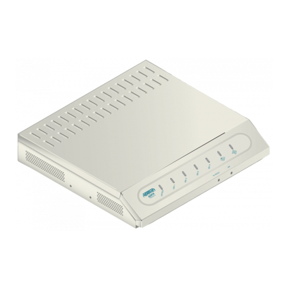
Page 9: Figure 1. Qdfr Front Panel
Quad Fiber Remote Unit GENERAL This practice is an installation and maintenance guide for the ADTRAN Quad Fiber Remote (QDFR) unit. The QDFR (P/N 1181307L7) front panel is illustrated in Figure 1. The QDFR rear panel is illustrated in Figure... -
Page 10: Table 1. Compliance Codes
Quad Fiber Remote (QDFR) Unit Installation and Maintenance Practice Features The QDFR provides the following features: • Software provisionable via menu access (no onboard switches) • Front panel indicators for the following: – Optical port status – T1 status for all channels –... -
Page 11: Installation
INSTALLATION After unpacking the QDFR, inspect it for damage. If damage has occurred, file a claim with the carrier then contact ADTRAN Customer Service. Refer to information. If possible, keep the original shipping container for returning the QDFR for repair or for verification of shipping damage. -
Page 12: Table 2. Front Panel Leds
Quad Fiber Remote (QDFR) Unit Installation and Maintenance Practice Label Indications Green Flashing (Red/Green) DS1 (1-4) Green Yellow Flashing (Red/Green) Flashing NEND/FEND Green Yellow Green TERM/MON Front Panel Pushbuttons The QDFR has two pushbuttons located on the front panel: • Channel Select ( CH SELECT •... -
Page 13: Figure 3. Rj-48C Pinout Configuration
LOOP CONNECTIONS The T1 loop connections are made through four RJ-48C type connectors. For each connector, transmit tip and ring are on pins 5 and 4, and receive tip and ring are on pins 2 and 1, respec- tively. The single-mode fiber is connected to the SC connector located on the back panel of the unit. -
Page 14: Table 3. Qdfr Provisioning Menu Defaults
Quad Fiber Remote (QDFR) Unit Installation and Maintenance Practice PROVISIONING The QDFR provides the ability to change provisioning options. and defaults for the provisioning options. Provisioning options are set independently for each of the DS1s. Table 3. QDFR Option Provisioning – Channel Options DSX-1 Line Buildout DSX-1/DS1 Line Code NIU Loopback... -
Page 15: Menu Structure
MENU STRUCTURE The menu structure for the QDFR is a layered menu tree. Each layer of the menu tree is displayed as a menu or a screen. Menu A menu is a display that provides numbered selections that are used to navigate to related menus, modify provisioning information, or display information screens. -
Page 16: Table 4. Adtran Qdf Main Menu Options
Shelf: Slot: Unacknowledged Alarms: Figure 4. ADTRAN QDF Main Menu The Main Menu options are shown in Table 4. ADTRAN QDF Main Menu Options Option Description QDF Unit Information Provisioning Status Auto In Service... -
Page 17: Troubleshooting
Table 4. ADTRAN QDF Main Menu Options (Continued) Option Description Alarm History Event History Troubleshooting Clear PM and Alarm Histories System PM/Screen Report Flash Upgrade Virtual Terminal Control QDF Unit Information Screen The QDF Unit Information screen (see and QDFR. The QDFC and QDFR name, CLEI code, part number, serial number, date of manufacturing, and software revision are included in this screen. -
Page 18: Figure 6. Provisioning Menu
Quad Fiber Remote (QDFR) Unit Installation and Maintenance Practice Provisioning Menu The Provisioning menu (Figure Shelf: Slot: Unacknowledged Alarms: The Provisioning menu contains the following submenus related to specific provisioning items: • Channel Options • Fiber PM Threshold Option • T1 PM Threshold Options •... -
Page 19: Figure 7. Status Screen
Status Screen The Status screen (Figure 7) provides information regarding the status of the QDFR. Shelf: Slot: Unacknowledged Alarms: ______ DSX-1 | QDFC | Ports 1-4 |______| Test Port: CH 1,Mon Rx Status Loopbacks --------- --------- CH 1: NONE CH 2: NONE CH 3: NONE... -
Page 20: Figure 10. Loopback Control Menu
Quad Fiber Remote (QDFR) Unit Installation and Maintenance Practice Loopback and Test Commands Menu Loopback and Test Commands menu QDFR. Shelf: Slot: Loopback Status: ---------------- Test Port: Figure 9. Loopback and Test Commands Menu Loopback Control Menu The Channel # Loopback Control menu QDFR and QDFC to the Network or Customer. -
Page 21: Figure 11. Test Jack Configuration Screen
The Test Jack Configuration screen back of the QDFR unit. This jack can “look at” a chosen port, in either direction as chosen by the user, as if it were a monitor jack (non-intrusive mode) or it can “break” a chosen port, in either direction, as if it were a equipment jack (intrusive mode). -
Page 22: Figure 13. Network Pattern Screen
Quad Fiber Remote (QDFR) Unit Installation and Maintenance Practice BERT Test Screen The Channel # BERT Test screen • (Re)start Pattern – Use this option to (re)start a test. • Stop Test – Use this option to manually stop a test. •... -
Page 23: Figure 15. Bert Inject Errors Screen
• Enter Test Timeout – This option displays the Network Timeout scree timeout can run for a specific duration by entering the hours and/or minutes, or can run indefinitely by entering 00:00. Shelf: Slot: Unacknowledged Alarms: Figure 14. Network Timeout Screen •... -
Page 24: Figure 17. Performance History Menu
Quad Fiber Remote (QDFR) Unit Installation and Maintenance Practice Self-Tests Screen Selecting Self-Tests performs tests of the QDFC and QDFR, with no additional user input. If all functions pass, the “Self Test Complete” message appears Shelf: Slot: Unacknowledged Alarms: Performance History Menu The Performance History menu the circuit. -
Page 25: Figure 18. Performance History Channel # Menu
Performance History Channel # Menu The Performance History Channel # menu channel. From this screen, the network or customer receiver may be selected. Shelf: Slot: Unacknowledged Alarms: Figure 18. Performance History Channel # Menu Performance History Fiber Menu The Performance History Fiber menu QDFR. -
Page 26: Figure 21. Channel Performance History Screen, From Customer
Quad Fiber Remote (QDFR) Unit Installation and Maintenance Practice The Channel Performance History of the DSX-1 Rx from the network is shown in Shelf: Slot: Unacknowledged Alarms: Channel 1 Performance History - DSX-1 Rx from Network - 24 Hour Data Line Data ES-L SES-L LOSS-L CV-L... -
Page 27: Figure 22. Scratch Pad, Circuit Id Menu
Scratch Pad, Circuit ID Menu The Scratch Pad, Circuit ID menu number, or identity of the users choosing. The scratch pad can be used to make specific notes or reminders. Shelf: Slot: Unacknowledged Alarms: Ch 1 Circuit ID = Ch 2 Circuit ID = Ch 3 Circuit ID = Ch 4 Circuit ID = Scratch Pad =... -
Page 28: Figure 24. T1 Alarm History Screen
Quad Fiber Remote (QDFR) Unit Installation and Maintenance Practice Alarm History Menu The Alarm History menu (Figure Threshold Crossing Alarms. A red alarm indicates a loss of signal or loss of framing, a yellow alarm indicates a remote alarm indication, and a blue alarm is an alarm indication signal. Shelf: Slot: Unacknowledged Alarms:... -
Page 29: Figure 26. Event History Screen
Channel T1 Threshold Alarm History Screen An individual Channel T1 Threshold Alarm History screen seconds, severely errored seconds, loss of signal seconds, code violation line, and code violation path. Shelf: Slot: Unacknowledged Alarms: LOCATION THRESH ALARM -------------------------------------------------------------------------------- QDFC ESL 15MIN (DSX-1) SESL 15MIN LOSSL 15MIN... -
Page 30: Figure 28. Troubleshooting Guidance Screen
Quad Fiber Remote (QDFR) Unit Installation and Maintenance Practice Troubleshooting Menu The Troubleshooting menu equipment in the circuit and presents them in both Real-Time and 7-Day historical format. The Definitions option from this menu provides definitions of terms and acronyms. Shelf: Slot: Unacknowledged Alarms:... -
Page 31: Figure 29. Clear Pm And Alarm Histories Prompt
The following line appears, to indicate that the PM and alarm histories are being erased: Clearing all Performance and Alarm History 61181307L7-5E Total Access System Adtran QDF Main Menu QDF Unit Information Provisioning Status Auto In Service... -
Page 32: Figure 30. System Pm/Screen Report Menu
Quad Fiber Remote (QDFR) Unit Installation and Maintenance Practice System PM/Screen Report Menu System PM/Screen Report menu Enable data logging now. Select Report Type or Press Escape to cancel: Full System/History Report Current Status Report System Configuration Report Alarm/Event History Figure 30. -
Page 33: Figure 32. Flash Upgrade, Y-Modem In Progress
Download QDFR via Y-Modem Menu The Download QDFR via Y-Modem menu computer connected to the craft access port to the QDFR. This file is downloaded to the QDFR. The file downloaded to the QDFR should be of the “.bin” file type only and is only provided for feature enhancements/additions and bug fixes. -
Page 34: Figure 33. Virtual Terminal Control Screen
Quad Fiber Remote (QDFR) Unit Installation and Maintenance Practice Virtual Terminal Control The Virtual Control screen allows control of remote unit provisioning from a QDR module. Select the Log into QDFR option from this screen and press session with a the far-end unit. When the remote session is complete, press terminate the session. -
Page 35: Table 5. Specifications
ADTRAN does not recommend that repairs be attempted in the field. Repair services may be obtained by returning the defective unit to ADTRAN. Refer to for further information. - Page 36 Quad Fiber Remote (QDFR) Unit Installation and Maintenance Practice This page is intentionally blank. 61181307L7-5E...
-
Page 37: Qdfr Loopbacks
QDFR Loopbacks FIBER LINE UNIT MAINTENANCE MODES This appendix describes operation of the optical fiber system with regard to detection of in- band and ESF facility data link loopback codes. Upon deactivation of a loopback, the T1 channel interface will synchronize automatically. Each T1 channel is independent of the others. -
Page 38: Table A-1. Loopback And Control Codes
Quad Fiber Remote (QDFR) Unit Installation and Maintenance Practice Loopback Control Codes A summary of control sequences is given in of 5 seconds to be detected and acted upon. In all control code sequences presented, the in-band codes are shown left-most bit transmitted first, and the ESF data link codes with right-most bit transmitted first. - Page 39 Table A-1. Loopback and Control Codes (Continued) Pattern Description 9393 Loopdown QDFC DS1 – either direction Loopdown QDFR DS1 – customer loopback always; will only loopdown QDFR network loopback if NIU is disabled Does not disarm units if they are armed D5D5 If unit is in loopback towards pattern, errors are periodically injected toward pattern as long as pattern is present...
- Page 40 Quad Fiber Remote (QDFR) Unit Installation and Maintenance Practice This page is intentionally blank. 61181307L7-5E...
-
Page 41: Rear Panel Ds1 Test Access
Rear Panel DS1 Test Access GENERAL Figure B-1 through Figure B-3 for the QDFR. The test jack can be provisioned to correspond to any of the four T1 channels. There are two options for selecting the T1 channel to be “connected” to the test jack. •... -
Page 42: Figure B-1. Dsx Mon, Tx To Customer
Quad Fiber Remote (QDFR) Unit Installation and Maintenance Practice MONITOR MODE Monitor Tx to Customer The Rx of the monitor BERT receives data from the TX point of the test jack, monitors the data that the customer’s equipment is receiving from the network equipment. Figure B-1. -
Page 43: Figure B-2. Dsx Mon, Rx From Customer
Monitor Rx from Customer The Rx of the monitor BERT receives data from the RX point of the test jack, monitors the data that the customer’s equipment is transmitting to the network equipment. Figure B-2. DSX MON, Rx from Customer To set up the QDFR for this mode, the following sequence must be performed: 1. -
Page 44: Figure B-3. Terminate Mode
Quad Fiber Remote (QDFR) Unit Installation and Maintenance Practice TERMINATE MODE Intrusive Tx to Customer and Rx from Customer This is an intrusive test and the original data path will be dis- rupted. The Tx of the BERT connects to the Tx of the test jack. The Rx of the BERT connects to the Rx of the test jack, Figure B-3. -
Page 45: Intrusive Tx To Network And Rx From Network
Intrusive Tx to Network and Rx from Network This is an intrusive test and the original data path will be dis- rupted. The Tx of the BERT connects to the Tx of the test jack. The Rx of the BERT connects to the Rx of the test jack, Figure B-3. - Page 46 Quad Fiber Remote (QDFR) Unit Installation and Maintenance Practice This page is intentionally blank. 61181307L7-5E...
-
Page 47: Warranty
Appendix C Warranty WARRANTY AND CUSTOMER SERVICE ADTRAN will replace or repair this product within the warranty period if it does not meet its published specifications or fails while in service. Warranty information can be found at www.adtran.com/warranty. Refer to the following subsections for sales, support, Customer and Product Service (CAPS) requests, or further information. - Page 48 ® Carrier Networks Division 901 Explorer Blvd. Huntsville, AL 35806...
Need help?
Do you have a question about the QDFR Unit and is the answer not in the manual?
Questions and answers